Download

1 / 37
430 likes | 758 Vues
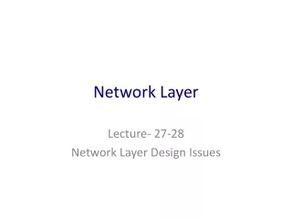
Goals: Understand Internet network layer concepts Understand Internet routing Understand Internet network layer protocols. Content: IP addressing Getting packet from source to destination Internet Protocol (IP) ICMP Intra- & Inter-AS routing Multicast routing. Network Layer.

E N D
Goals: Understand Internetnetwork layer concepts Understand Internet routing Understand Internet network layer protocols Content: IP addressing Getting packet from source to destination Internet Protocol (IP) ICMP Intra- & Inter-AS routing Multicast routing Network Layer Network Layer
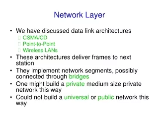
Host, router network layer functions: • ICMP protocol • error reporting • router “signaling” • IP protocol • addressing conventions • datagram format • packet handling conventions • Routing protocols • path selection • RIP, OSPF, BGP routing table The Internet Network layer Transport layer: TCP, UDP Network layer Link layer Physical layer Network Layer
IP address: 32-bit identifier for host, router interface interface: connection between host/router and physical link routers typically have multiple interfaces host may have multiple interfaces IP addresses associated with interface, not host or router 223.1.1.2 223.1.2.2 223.1.2.1 223.1.3.2 223.1.3.1 223.1.3.27 IP Addressing 223.1.1.1 223.1.2.9 223.1.1.4 223.1.1.3 223.1.1.1 = 11011111 00000001 00000001 00000001 223 1 1 1 Network Layer
IP address: network part (high order bits) host part (low order bits) What’s a network ? (from IP address perspective) device interfaces with same network part of IP address can physically reach each other without intervening router IP Addressing 223.1.1.1 223.1.2.1 223.1.1.2 223.1.2.9 223.1.1.4 223.1.2.2 223.1.3.27 223.1.1.3 LAN 223.1.3.2 223.1.3.1 network consisting of 3 IP networks (for IP addresses starting with 223, first 24 bits are network address) Network Layer
multicast address 1110 network host 110 network 10 host IP Addresses class 1.0.0.0 to 127.255.255.255 A network 0 host 128.0.0.0 to 191.255.255.255 B 192.0.0.0 to 239.255.255.255 C 240.0.0.0 to 247.255.255.255 D 32 bits What is POSTECH’s network address? What is your research lab’s subnet address? Network Layer
IP packet: 223.1.1.1 223.1.2.1 B E A 223.1.1.2 source IP addr 223.1.2.9 header fields dest IP addr 223.1.1.4 data 223.1.2.2 223.1.3.27 223.1.1.3 223.1.3.2 223.1.3.1 Dest. Net. next router Nhops 223.1.1 1 223.1.2 223.1.1.4 2 223.1.3 223.1.1.4 2 Getting a packet from source to dest. routing table in A • packet remains unchanged, as it travels source to destination • addr fields are of interest here Network Layer
223.1.1.1 223.1.2.1 E B A 223.1.1.2 223.1.2.9 223.1.1.4 223.1.2.2 223.1.3.27 223.1.1.3 223.1.3.2 223.1.3.1 Dest. Net. next router Nhops 223.1.1 1 223.1.2 223.1.1.4 2 223.1.3 223.1.1.4 2 Getting a packet from source to dest. header fields data 223.1.1.1 223.1.1.3 • Starting at A, given IP packet addressed to B: • look up net. address of B • find B is on same net. as A using subnet mask • link layer will send packet directly to B inside link-layer frame • B and A are directly connected Network Layer
223.1.1.1 223.1.2.1 E B A 223.1.1.2 223.1.2.9 223.1.1.4 223.1.2.2 223.1.3.27 223.1.1.3 223.1.3.2 223.1.3.1 Dest. Net. next router Nhops 223.1.1 1 223.1.2 223.1.1.4 2 223.1.3 223.1.1.4 2 Getting a packet from source to dest. header fields data 223.1.1.1 223.1.2.2 Starting at A, dest. E: • look up network address of E • E on different network • A, E not directly attached • routing table: next hop router to E is 223.1.1.4 • link layer sends packet to router 223.1.1.4 inside link-layer frame • packet arrives at 223.1.1.4 • continued….. Network Layer
Dest. next 223.1.1.1 network router Nhops interface 223.1.2.1 E B A 223.1.1 - 1 223.1.1.4 223.1.1.2 223.1.2 - 1 223.1.2.9 223.1.2.9 223.1.1.4 223.1.3 - 1 223.1.3.27 223.1.2.2 223.1.3.27 223.1.1.3 223.1.3.2 223.1.3.1 Getting a packet from source to dest. header fields data 223.1.1.1 223.1.2.2 Arriving at 223.1.1.4, destined for 223.1.2.2 • look up network address of E • E on same network as router’s interface 223.1.2.9 • router, E directly attached • link layer sends packet to 223.1.2.2 inside link-layer frame via interface 223.1.2.9 • packet arrives at 223.1.2.2!!! Network Layer
IP packet format IP protocol version number 32 bits total datagram length (bytes) header length (bytes) type of service head. len ver length for fragmentation/ reassembly fragment offset “type” of data flgs 16-bit identifier max number remaining hops (decremented at each router) upper layer time to live Internet checksum 32 bit source IP address 32 bit destination IP address upper layer protocol to deliver payload to E.g. timestamp, record route taken, specify list of routers to visit. Options (if any) data (variable length, typically a TCP or UDP segment) Network Layer
network links have MTU (max. transfer unit) - largest possible link-level frame. different link types, different MTUs large IP packet divided (“fragmented”) within net one packet becomes several packet “reassembled” only at final destination IP header bits used to identify, order related fragments IP Fragmentation and Reassembly fragmentation: in: one large packet out: 3 smaller packets reassembly Network Layer
length =1500 length =1500 length =4000 length =1000 ID =x ID =x ID =x ID =x fragflag =0 fragflag =0 fragflag =1 fragflag =1 offset =0 offset =1500 offset =0 offset =3000 IP Fragmentation and Reassembly One large packet becomes several smaller packets Network Layer
ICMP: Internet Control Message Protocol • Internet Control Message Protocol (ICMP), RFC792 • The purpose of ICMP messages is to provide feedback about problems in the IP network environment • Delivered in IP packets • ICMP message format • 4 bytesof ICMP header and optional message Network Layer
ICMP Functions • To announce network errors • If a network, host, port is unreachable, ICMP Destination Unreachable Message is sent to the source host • To announce network congestion • When a router runs out of buffer queue space, ICMP Source QuenchMessage is sent to the source host • To assist troubleshooting • ICMP Echo Message is sent to a host to test if it is alive - used by ping • To announce timeouts • If a packet’s TTL field drops to zero, ICMP Time Exceeded Message is sent to the source host - used by traceroute Network Layer
ICMP Problems • ICMP has also received bad press from denial of service (DoS) attacks and because of the number of sites generating monitoring traffic • ICMP messages may be blocked (i.e., dropped) by firewall or processed at low priority by router • As a consequence some ISPs disable ICMP even though this potentially causes poor performance and does not comply with RFC1009 (Internet Gateway Requirements) • In spite of these limitations, ICMP is still most widely used in active network measurements Network Layer
ICMP Messages TypeCodedescription 0 0 echo reply (ping) 3 0 dest. network unreachable 3 1 dest host unreachable 3 2 dest protocol unreachable 3 3 dest port unreachable 3 6 dest network unknown 3 7 dest host unknown 4 0 source quench (congestion control - not used) 8 0 echo request (ping) 9 0 route advertisement 10 0 router discovery 11 0 TTL expired 12 0 bad IP header Network Layer
Routing in the Internet • The Global Internet: A hierarchy of Autonomous Systems (ASs) (enterpriseASs interconnected through ISP’s ASs) • Two level routing: Intra-AS: each enterprise is responsible for its intranet routing policy Inter-AS: uses the standard routing protocol (e.g., BGP) Network Layer
Intra-AS Routing • Also known as Interior Gateway Protocol (IGP) • Most common IGPs: • RIP: Routing Information Protocol (IETF) • OSPF: Open Shortest Path First (IETF) • IGRP: Interior Gateway Routing Protocol (Cisco) Network Layer
RIP (Routing Information Protocol) • Distance vector type scheme • Included in BSD-UNIX Distribution in 1982 • Distance metric: # of hops (maximum 15 hops) • Distance vector: exchanged every 30 sec via a Response Message (also called Advertisement) • Each Advertisement contains up to 25 destination nets • IETF RFC 1058 - http://www.ietf.org/rfc/rfc1058.txt Network Layer
RIP Example D’s Table before A’s Advertisement Dest. Net. next router Nhops Routers labeled A, B, C, D, … Networks labeled 1, 10, 20, 30, ... 1 A 2 20 B 2 30 B 7 10 -- 1 ... ... ... A’s Advertisement Dest. Net. next router Nhops 30 C 4 1 -- 1 10 -- 1 ... ... ... D’s table after A’s advertisement Dest. Net. next router Nhops 1 A 2 20 B 2 30 A 5 ... ... ... Network Layer
RIP: Link Failure and Recovery • If no advertisement heard after 180 sec, neighbor/link is assumed to be dead • Routes via the neighbor are invalidated; new advertisements sent to neighbors • Neighbors in turn send out new advertisements if their tables changed • Link failure info quickly propagates to the entire net Network Layer
RIP Table processing • RIP routing tables managed by an application process called routed (daemon) • advertisements encapsulated in UDP packets (reliability not required; advertisements are periodically repeated) Network Layer
RIP Table example • To get routing table on Unix/Win, type netstat -rn • e.g.,a RouterRIP table: • 3 attached class C networks (LANs) via fa0, le0 and qaa0 • Router only knows routes to attached LANs • default is the default gateway “to go up” • Route multicast address: 224.0.0.0 • 1st entry: Loopback interface (for debugging) • Learn to use Netstat by examples: http://www.cs.unh.edu/cnrg/lin/linuxProject/resource/netstatCookbook.htm Destination Gateway Flags Ref Use Interface --------------- ----------------- ----- ---- ------- --------- 127.0.0.1 127.0.0.1 UH 0 26492 lo0 192.168.2. 192.168.2.5 U 2 13 fa0 193.55.114. 193.55.114.6 U 3 58503 le0 192.168.3. 192.168.3.5 U 2 25 qaa0 224.0.0.0 193.55.114.6 U 3 0 le0 default 193.55.114.129 UG 0 143454 Network Layer
OSPF (Open Shortest Path First) • “open”: publicly available protocol (IETF) • uses the Link State (LS) algorithm, i.e., • LS packet dissemination; • topology map at each node; • route computation using the Dijkstra’s algorithm • OSPF advertisement carries one entry per neighbor router (gives link state) • Advertisements disseminated to the ENTIRE AS (via flooding) Network Layer
OSPF “advanced” features (not in RIP) • Security. All OSPF messages are authenticated (to prevent malicious intrusion); TCP connections used • Multiple same-cost paths allowed (only one path must be chosen to carry all traffic in RIP) • Multiple cost metrics for different TOS for each link (e.g., satellite link cost set “low” for best effort; high for real time) • Integrated uni- and multicast support. Multicast OSPF (MOSPF) uses the same topology database as OSPF • Hierarchical OSPF in single AS (large routing domain) Network Layer
Hierarchical OSPF • An OSPF AS: Two level hierarchy (local area and backbone) • Link state advertisements do not leave respective areas • Nodes in each area have detailed area topology; they only know direction (shortest path) to networks in other areas • “Internal routers” perform intra-AS routing only • “Area Border routers” route packets to other areas • “Backbone routers” run an OSPF routing alg. limited to the backbone • “Boundary routers” connect to other ASs Network Layer
IGRP (Interior Gateway Routing Protocol) • CISCO proprietary; successor of RIP (mid 80’s) • Distance Vector, like RIP • Several cost metrics (delay, bandwidth, reliability, load, etc.) • Uses TCP to exchange routing updates • Routing tables exchanged only when costs change • Loop free routing achieved by using a Distributed Updating ALgorithm (DUAL) • In DUAL, after a distance increase, the routing table is frozen until all affected nodes have learned of the change • http://www.cisco.com/en/US/tech/tk365/technologies_white_paper09186a00800c8ae1.shtml Network Layer
Inter-AS Routing • BGP (Border Gateway Protocol): the de facto standard • Each Border Gateway broadcasts to neighbors (peers) the entire path (i.e., sequence of AS’s) to destination • For example, gateway X may store the following path to destination Z: Path (X,Z) = X,Y1,Y2,Y3,…,Z Network Layer
Border Gateway Protocol (BGP) • Now, suppose Gwy X sends its path (X,Y1,Y2,Y3,…,Z) to peer Gwy W • Gwy W may or may not select the path offered by Gwy X, because of cost, policy or loop prevention reasons • If Gwy W selects the path advertised by Gwy X, then: Path (W,Z) = W, Path (X,Z) Note: path selection based not so much on cost (e.g.,# of AS hops), but mostly on administrative and policy issues (e.g., do not route packets through competitor’s AS) Network Layer
Border Gateway Protocol (BGP) • Peers exchange BGP messages using TCP • BGP defines 4 types of messages: • OPEN: opens a TCP connection to peer and authenticates sender • UPDATE: advertises new path (or withdraws old) • KEEPALIVE: keeps connection alive in absence of UPDATES; also serves as ACK to an OPEN request • NOTIFICATION: reports errors in previous msg; also used to close a connection • IETF RFC 1771 - http://www.ietf.org/rfc/rfc1771.txt Network Layer
Why Intra- and Inter-AS routing different? (1/2) • Policy: • Inter: concerned with policies (eg, which provider to select/avoid) • Intra: under same administrative control, so, policy-based routing is less important • Scaleability • Inter: ability of routing alg. and table to scale for routing among large numbers of networks • Intra: scalability is less of a concern within an AS. A large AS can be divided into two ASs, e.g., “areas” in OSPF Network Layer
Why Intra- and Inter-AS routing different? (2/2) • Performance: • Inter: routing is policy-oriented; quality of routes is secondary. Also, it is difficult to propagate performance metrics efficiently (latency, privacy, etc.). • Intra: focused on performance metrics; needs to keep costs low. • We need BOTH! Network Layer
Multicast Routing • Multicast: delivery of a packet to a group of receivers • Multicasting is becoming increasingly popular in the Internet (e.g., video on demand, IPTV, multi-player online games) • Multiple unicast vs. multicast Network Layer
Multicast Group Address • M-cast group address “delivered” to all receivers in the group • Internet uses Class D(240.0.0.0 to 247.255.255.255) for m-cast • M-cast address distribution, etc. managed by IGMP (Internet Group Management Protocol) Network Layer
IGMP Protocol (RFC 2236) • IGMP (Internet Group Management Protocol) operates between router and local hosts, typically on a LAN • Router queries the local hosts for m-cast group membership info • Router “connects” active hosts to m-cast tree via m-cast protocol • Hosts respond with membership reports: actually, the first host which responds (at random) speaks for all • Host issues “leave-group” msg to leave; this is optional since router periodically polls anyway Network Layer
IGMP message types IGMP Message typeSent byPurpose membership query: general router query for current active multicast groups membership query: specific router query for specific m-cast group membership report host host wants to join group leave group host host leaves the group Network Layer
You now hopefully have: a good understanding of the Internet network protocols and issues IP addressing, format & issues Intra-AS routing protocols RIP OSPF IGRP Inter-AS routing BGP Multicast routing IGMP Summary Network Layer