Download
1 / 75
760 likes | 958 Vues
Session 4 KY Type 1 End Treatment ET-PLUS Slide 6 by Trinity Highway Products SKT-SP Slide 63 by Road Systems. How do you know which version of a Proprietary Guardrail End Treatment KY is Using?. Go to the KYTC Div of Design Home Page http://transportation.ky.gov/Highway-Design

E N D
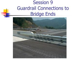
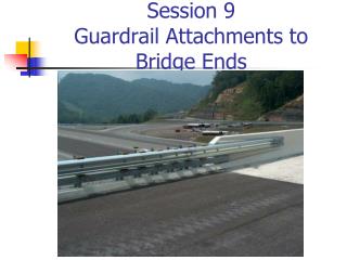
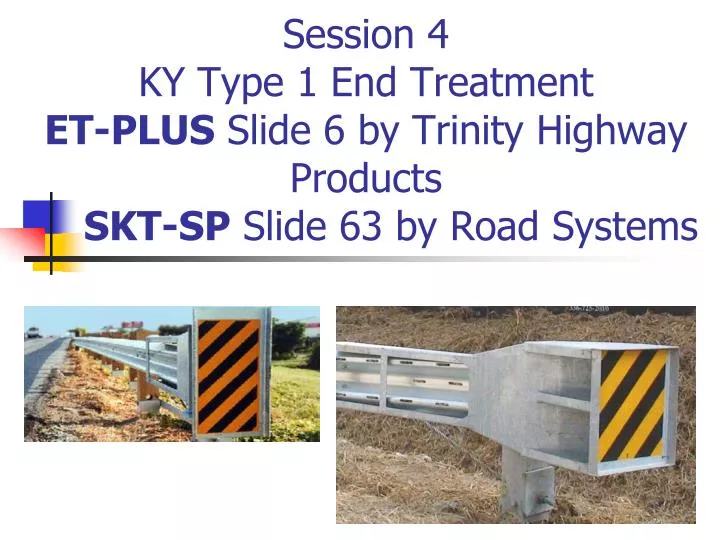
Session 4KY Type 1 End TreatmentET-PLUS Slide 6 by Trinity Highway ProductsSKT-SP Slide 63 by Road Systems
How do you know which version of a Proprietary Guardrail End Treatment KY is Using? • Go to the KYTC Div of Design Home Page http://transportation.ky.gov/Highway-Design • On the lower right click on Standard Drawing • Brings up: • Standard Drawings • Active Sepia List • Approved Shop Drawings - Click • The drawings show the version PLUS, SP, 27 etc. • Basic Info – very useful
http://transportation.ky.gov/Highway-Design Design Home PageStandard Drawings Lower Right
Standard DrawingsActive Sepia ListApproved Shop Drawings Click
The ET-Plus KY Uses is50’, 7 SYT Post & 1 HBA Post The Title Block Details which ET-Plus Model KY is using
ET-Plus Parts ListYou can learn a lot just looking at the Parts List and the Drawing
Standard Drawing RBI-004Installation of Guardrail End Treatment Type 1
Installation Instructions for Proprietary Guard Rail End Terminals • This Std Draw Note appears on each Proprietary End Treatment used in KY - “The Manufacturer SHALL furnish two (2) sets of shop plans to the contractor with each installation” • Each Proprietary End Treatment “see shop drawings” • Added to Sect 719.03 of 2012 Std Specs: “Proprietary end treatments SHALL be installed according to the manufacturer’s assembly or installation instructions” • SHOULD NOT LET THE CONTRACTOR BEGIN INSTALLATION BEFORE SUPPLYING YOU WITH THESE SHOP PLANS & INSTALLATION INSTRUCTIONS – Both you and the contractor need these documents to properly do your jobs of installing and inspection propriety guardrail end terminals
Type 1 Trinity – ET-Plushttp://www.highwayguardrail.com/products/etplus.html
Type 1 ET-PlusStandard Drawing Note • “The Manufacture Shall Furnish Two (2) Sets of Shop Plans to the Contractor with Each Installation” • For the ET-Plus this is on line at • http://www.highwayguardrail.com/products/pdfs/ETPlus-Manual.pdf Call 1-800-527-7976 if you do NOT Understand Manual • This Manual is cumbersome and somewhat hard to follow
http://www.highwayguardrail.com/products/pdfs/ETPlus-Manual.pdfhttp://www.highwayguardrail.com/products/pdfs/ETPlus-Manual.pdf
ET-Plus - Absorbs Energy by Extruding the Rail Thru Impact Head and Knocking Down Post
ET-Plushttp://www.highwayguardrail.com/products/etplus.html • Energy Absorbing End Treatment • 50 feet long • Post 1 - HBA Post (Hinged Break-Away) • Post 2-8 7 SYT Post (Steel Yielding Terminal) • Has a Strut between Post 1&2 • No Tube or Soil Plates • Standard Guardrail begins at Post 9
ET-Plushttp://www.highwayguardrail.com/products/etplus.html • Do Not attach Guardrail to Post 1 • Under no circumstances shall the guardrail within the ET-Plus Pay Limit be Curved – see Installation Instructions
ET-Plus Installing HBA Post-Bottom Post 1 Install the Bottom of the HBA Post such that the large hole 13/16” is placed downstream (away from the Impact Head)
ET-Plus Installing HBA Post-Top Post 1 • Align the Holes of the Post Plates (either side of Ears) on the Top and Bottom Post • Insert a 3/8” x 2” Hex Head Bolt through the 7/16” hole in the Post Plates (Ears) with washer and lockwasher under the 3/8” Nut (one bolt assembly on each side of Post) • Note 3/8” Bolts can be installed with nuts inside or outside of Post Plates
ET-Plus Installing HBA - Top Post 1 Are Lock Washer & Washer on??
ET-Plus Installing HBA Post-Top Post 1 • On the side opposite the Strut - Insert a ¾” x 2 ½ ” Hex Head Bolt through the 13/16” hole in the Post Plates with washer and lockwasher under the ¾” Nut • Note ¾ ” Bolts can be installed with nuts inside or outside of Post Plates • DO NOT install the ¾” Bolt on the Strut Side until installing the Strut
ET-Plus Installing HBA Post - Top Post 1Are Lockwasher & Washers on??
Final Assembly @ Base of Post 1Washer but does not have Lockwasher
ET-PlusPost 2 – 8 SYT Post • If properly Graded, drive all the 6’ SYT Post to the optimum depth where centers of the 4 Yielding Holes through the Flanges are at the Ground Line • Note: Post 2 does NOT have an offset block • Note: Post 3-8 receive 8” offset blocks
ET-PlusInstalling the Strut Post 1 • Place Angle Strut on the Flange of the HBA Post 1 with ¾” Hex Head Bolt placed through the top and bottom Post Plates and connect with a ¾” Washer and Lockwasher under the ¾” Nut. • Note: Strut can be placed with one of the leg flat or leg edge on the ground • Note: Strut can be installed on traffic side or field side of the Post
Installing the Strut Post 1Again where is the Washer & Lockwasher??
ET-PlusInstalling the Strut Post 2 • Place 2 – 7/16” Hex head Bolts with Washer into the two Slotted Holes of the Strut • Place a Lockwasher and Nut on the ends of each of the Inserted Bolts • Tighten Nuts to snug position
ET-PlusInstalling the Strut Post 2 Washers are Important Incorrect - Loose Fit Without Washer & Lockwasher Correct Tight Fit With Washer
ET-PlusInstall Offset Blocks & Rail PanelsPost 3 - 8 • 25’ or 12’6” Rail Panels are acceptable • Splice the rail Panels with 8 - 5/8” x 1 ¼” HGR Splice Bolts and Nuts • Do NOT connect Rail Panel @ Post 1 • NO Offset Blocks @ Post 1 or 2 • Post 3-8 Insert 5/8” x 10” HGR Bolt thru Rail Panel, 8” Offset Block and SYT Post • Connect with 5/8” Round Washer and HGR Nut
Post 2 No Offset BlockPost 3-8 8” Offset BlockComposite or Wood
ET-Plus Installing Rail Panel to Post 2 • NO Offset Block @ post 2 • Insert 5/8” x 1 ¼” HGR Bolt through the Rail Panel and SYT Post @ Post 2 • Connect with 5/8” Round Washer and HGR Nut
ET-PlusInstalling the Cable Anchor Assembly • Secure Cable Anchor Assembly to the Rail by Inserting the Square Protruding Hooks/Lugs into Square Holes in Rail Panel toward Post 1. Secure by pulling the Bracket toward the Impact head insuring the Hooks/Lugs are well Seated into the Square Holes.
ET-PlusInstalling the Cable Anchor Assembly • Slide one end of Cable into the Cable Anchor Bracket and the other end into Post 1 • Place a 1” Washer and Hex Nut on the Bracket End near Post 2 and tighten until at least 2 Threads are showing • Place Bearing Plate on Impact Side of Post 1 where Cable extends through Post 1 • Bearing Plate must have Long Dimension (5”) Up
Bearing Plate with Tabs on both sides to keep Bearing Plate Oriented with 5” UP
ET-PlusInstalling the Cable Anchor Assembly • Place 1” Washer and Hex Nut on the end of the Cable extending through Post 1 • Restrain the Cable with locking pliers at the end of the Cable being tightened • Tighten the Hex Nuts on the Cable Ends until TAUT – it is considered TAUT when Cable does not deflect more than 1” when pressure is applied
Tighten Anchor Cable – Using Vice Grips
ET-PlusInstalling the Cable Anchor Assembly • Shank portion of Anchor Cable MUST BE positioned so it bears on the bottom edge of the web of the HBA Post (Post 1) • Shank portion of Cable must also be centered Horizontally so the Bearing Plate bears uniformly on both Fingers of Post 1
ET-PlusInstalling the Extruder Head • Rail feeds out the Extruder Head away from traffic – Arm points away from traffic • Push the Extruder Head as far as it will go on the Rail panel, making sure the Rail is in the Channel Chute • Place the Extruder head against the HBA Post (Post 1) parallel to the ground
ET-PlusProperly Installed Extruder HeadPushed all the way on