Download
1 / 11
110 likes | 262 Vues
1RE03 Two Wheeled Balancing Bot. Tilt is sensed by sensors(accelerometer and gyroscope). Components. Arduino(ATmega 328) Two axis Accelerometer(MMA6361L) Gyroscope (LY510A) L298D motor driver IC LM 7805 IC 12V 150 RPM Johnson motor x 2 11.1V Li-ion battery. Sensors.

E N D
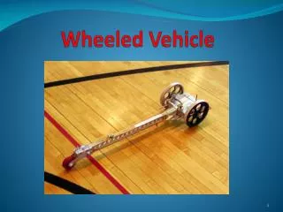
1RE03 Two Wheeled Balancing Bot
Components • Arduino(ATmega 328) • Two axis Accelerometer(MMA6361L) • Gyroscope (LY510A) • L298D motor driver IC • LM 7805 IC • 12V 150 RPM Johnson motor x 2 • 11.1V Li-ion battery
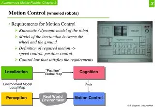
Sensors Accelerometer • Tilt angle is calculated using accelerometer and gyroscope independently. • The accelerometer cannot differentiate the horizontal acceleration of the bot from gravity, which gives error in the tilt angle. • Gyroscope gives the angular velocity, which on integrating gives the tilt angle.
Graph • This is the first integrated output of the gyroscope giving the tilt angle. • After some time, considerable drift is observed.
Complementary Filter • A dynamic fluctuation is observed in the accelerometer readings. • Gyroscope readings drift with time. • A combination of both the readings is done using complementary filter.
Complementary Filter • Low pass filter is applied to accelerometer. • High pass filter is applied to gyroscope. • Mathematically, complementary filter looks like this: Tilt angle = (1-a)*gyroscope + a*accelerometer; Gyroscope = tilt angle; where a is a small number
Complementary Filter • Complementary filter filters out the fluctuations of the accelerometer and also corrects the gyroscopic drift.
Motor Driver L298D motor driver ckt. Johnson motors L298D driver gives 2A current per channel.
Chassis First chassis Final chassis • Different combinations were tried by varying the position of the mass(batteries). • Height of the bot was reduced.
PID Controller • PD controller has been used for balancing the bot. • For greater precision we have used tan of tilt angle. • Mathematically, the PD controller looks like: pwm = kp * tan(tilt angle) + kd * d/dt (tilt angle);