Download
1 / 27
290 likes | 469 Vues
CAPACITORS 90523. NCEA Level 3 Physics. CAPACITORS. Electric field strength Capacitors Capacitance & Charge Energy in capacitors Capacitors in series and parallel RC Circuits Charging a capacitor Discharging a capacitor Time constant. ELECTRIC FIELD STRENGTH. What is it?.

E N D
CAPACITORS90523 NCEA Level 3 Physics
CAPACITORS • Electric field strength • Capacitors • Capacitance & Charge • Energy in capacitors • Capacitors in series and parallel • RC Circuits • Charging a capacitor • Discharging a capacitor • Time constant
ELECTRIC FIELD STRENGTH What is it? ANS: Is the force that an electric charge experiences within a specific space (field). Symbol : E Units: Newtons per Coulomb (NC-1) E = F/q Remember from level 2 that electric fields act either inward or outwards dependent on the charge: Field lines represented with an arrow hence are vectors. Field lines are stronger when closer together. + -
FIELD LINES BETWEEN PLATES If parallel plates are charged then a uniform electric field is then established: - - - - - - - - - - - - - - - - - - - - B D C A + + + + + + + + + + + + + + + + + + Note: The field strength is the same wherever the charge happens to be e.g. A; B or C. At the edges “D” the field strength is weaker as the field lines are longer, the plates being further apart. If a charge is moved from the negative plate to the positive then potential energy (EP)is produced or a potential difference set up ‘V’. This is also dependent on the distance ‘d’ between the plates thus two equations can be produced: EP = qV E = V/d
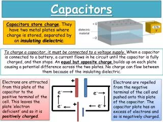
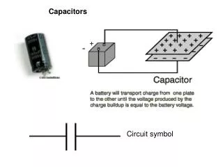
CAPACITORS What is it? ANS: It is an electrical component that can store electrical charge and release it some time later. Symbol : C Units: Farad (F) Everyday capacitors are measured in either F (10-6); nF (10-9);pF (10-12). C USES 1. Storing energy as in flash photography 2. Time delays in electronic circuits 3. As filters in electronic circuits 4. In tuning circuits Often made like a swiss roll by rolling metal plates with a insulator (dielectric)in between and wires attached to each plate.
BASIC CONSTRUCTION The Parallel Plate Capacitor TWO OPPOSITELY CHARGED CONDUCTORS SEPARATED BY AN INSULATOR - WHICH MAY BE AIR CONDUCTOR CONDUCTOR + - INSULATOR (DIELECTRIC)
WHAT DOES A CAPCITOR DO? The battery causes the flow of electrons to accumulate on one plate and attracts an equal number of electrons fro the other plate, leaving the plates oppositely charged. d E = electric field strength - + - + - + + - • When fully charged: • Flow of e- stops. • Both plates equal & oppositely charged. • Pd across plates, ‘V’ = Vsupply. • Electric field, ‘E’ exists between plates E = V/d. - + + - + - + - - +
Example 1: A capacitor is made of two thin metal sheets separated by a distance of 1.0mm. It is connected to a 12V battery. Calculate the electric field strength between the plates. SOLUTION: E = V/d = 12 / 1.0 x 10-3 = 12000Vm-1 READ INFORMATION Page 139 RUTTER
CAPACITANCE & CHARGE This is the amount of charge a capacitor can store when connected across a potential difference of 1 volt. Obviously the larger the capacitor the more charge it can contain. The capacitance (C) of a capacitor which stores a charge, ‘Q’ coulombs on each plate when connected across a supply of volts, ‘V’, is given by: C = Q/V Capacitors have a finite voltage at which they work at. If the voltage is exceeded then the dielectric will melt and the plates suddenly come into contact. Short circuit, capacitor explodes!! BOOM
Charge stored [Q] depends on p.d. [Volts] applied [V] Q Gradient = C V Hence C = Q/V Remember that the capacitance, C, is defined as “the charge required to raise the potential by one volt” EXERCISES Page 141 – 142 RUTTER
Example 2: How much charge is stored on the plates of a 100F capacitor connected to a 12V battery? SOLUTION: Q = C x V = 100x10-6 x 12 = 1.2x10⁻³ C
WHAT FACTORS DETERMINE CAPACITANCE? • Depend upon three factors: • The area, A, of the parallel plates. • The distance, d, separating the plates. • The properties of the dielectric material between the plates. Constant = absolute permittivity of free space (o) 0 = 8.84x10⁻¹² Fm-1 • Plates that have a greater area can store more charge, thus: • Plates that are closer together can store more charge, thus: C A C 1/d C = (oA) d C = constant x A/d
Example 3: A student wishes to make a capacitor of 1.0F using parallel plates 1.0mm apart in air. Find the area of the plates. SOLUTION: C = (O x A) / d A = (C x d) / O = (1.0 x 1.0x10-3) / 8.84x10-12 = 1.13x10⁸ m2 = 1.1x10⁸ m2
THE DIELECTRIC CONSTANT: Different materials insulate at differing amounts thus changing the capacitance, called dielectric effect. The dielectric constant (r) gives the proportion by which ‘C’ increases when dielectric placed between the plates. Area of Plate overlap = A Medium relative permittivity = r d = plate separation d 0 = the permittivity of free space = 8.86. X 10-12 F m-1 For air or a vacuum, r = 1
The dielectric constant does not a have a unit as it is the ratio between two capacitance values: r = Cdielectric Cair Examples of dielectric constants include: EXERCISES Page 144 – 145 RUTTER
Example 4: A parallel plate capacitor with air between its plates has capacitance 1.1nF. A sheet of polystyrene is placed between the plates. Calculate the new capacitance. SOLUTION: Cd = r x Ca = 2.5 x 1.1nF = 2.75nF = 2.8nF PRACTICAL: Factors affecting the capacitance of a pair of parallel plates. Page 143 RUTTER.
RC CIRCUITS CHARGING A CAPACITOR: An RC circuit is one that contains a resistor, ‘R’ and a capacitor, ‘C’. R V C CURRENT: When a capacitor begins to charge there is a massive flow of charge to the negative plate. This then decreases with time as repulsion from that plate pushes electron away. VOLTAGE: When the capacitor is empty there is zero charge stored. As electrons rush in there is a huge build up of energy. This begins to level out as repulsion denies entry of any further charge.
From this two graphs can be drawn for the charging of a capacitor with relation to what happens to current ‘I’ and voltage ‘V’. Imax VC Amps Volts 0 time CURRENT GRAPH VOLTAGE GRAPH Current starts at maximum Imax and then decreases to zero as the negative plate fills up with negative charge. Repulsion pushes against the force of the battery Voltage starts at zero and rapidly increases until it begins to reach maximum. Now repulsion prevents any further charge entering so the energy remains constant.
DISCHARGING A CAPACITOR: When a capacitor discharges the voltage and current graphs are the same. They start at a maximum and follow the inverse curves down towards zero, although it is worth noting that they don’t reach zero. Volts, V Current I V0 I0 0 Time, t Time, t Explain what is happening in each of these graphs and why they are the same. EXERCISES: Page 146 – 147 RUTTER
TIME CONSTANT: Time constant is the measure of time it takes for a capacitor to reach 63% of the total amount of voltage or current that it can store/release depending on whether it is charging/discharging. The larger , the slower the process. It is given the term tau, ‘’ and is measured in seconds, ‘s’. The formula for time constant is: • Where: • = time constant (s) R = resistance (Ω) C = capacitance (F) = RC As the voltage never reaches max or zero, then the total time taken can’t be measured hence that is why 63% of the time is used. (Same for current) EXERCISES: Page 148 – 149 RUTTER
Example 7: A 100F capacitor connected to a 10V battery is used with a 2.0MΩ resistor to automatically shut off a calculator. The capacitor, initially charged to 10V, discharges through the resistor whenever the buttons are not being pushed. The calculator will turn off when the capacitor voltage falls to 3.7V. What time will this take? SOLUTION: The capacitor voltage falls by 10 – 3.7 = 6.3V, which is 63% of the initial voltage and so will take one time constant. = RC = 100x10-6 x 2.0x106 = 200s PRACTICAL: The time constant for a capacitor-resistor series circuit Page 232-233 S & C.
THE ENERGY STORED IN CAPACITOR: As charge, Q, is packed onto the plates work needs to be done. Repulsive forces want to push the electrons away from the negative plate towards the positive. The battery supplies the push, energy, to pack these electrons. The push, pd, the battery has the greater the capacitance, C. Thus energy provided by the cell must equal: E = Q x V For a capacitor V vs Q is a straight line graph Area under graph = ½ x Q x V Area under graph = energy change = Q x V V V Q Q Energy stored in capacitor Energy provided by cell
As capacitance is the amount of stored charged then the energy inside a capacitor then two formulae can be produced. EP = ½CV2 EP = ½QV [Substituting Q = CV into EP] EP = ½Q2/C [Substituting V = Q/C into EP = ½QV] EXERCISES: Page 150 – 151 RUTTER
Example 5: • The energy from a 1100F capacitor is used to operate a photographer’s flash bulb. The capacitor is charged by a 9.0V battery. Calculate: • The energy stored in the capacitor. • The energy delivered by the battery. • Account for the difference in these two energies. SOLUTION: a. The energy stored in the charged capacitor is: EP = ½CV2 = 0.5 x 1100x10-6 x 9.02 = 0.045J b. The energy provided by the battery is twice the energy stored in the capacitor energy from the battery = 2 x 0.04455 = 0.089J c. The flow of charge while the capacitor is charging will cause energy to be changed to heat in the resistance of the circuit.
CAPACITORS IN SERIES & PARALLEL: V V SERIES PARALLEL - - + + Q1 C1 V1 V2 C2 Q- Q+ Q- Q+ Q2 C1 C2 Charge on each capacitor is the same. V = V1 + V2 For two or more capacitors: Voltage across each capacitor same as, V, of cell. Q = Q1 + Q2 For two or more capacitors: 1 = 1 + 1 …………. Cp = C1 + C2 ………. Cs C1 C2 EXERCISES: Page 152 – 153 RUTTER
Example 6: Calculate the equivalent capacitance of the network shown. 4F SOLUTION: For the two capacitors in parallel: Cp = 4F + 2F = 6F 12F 2F So the network is equivalent to 6F and 12F capacitors connected in series. 1/Cp = 1/C1 + 1/C2 = 1/12 + 1/6 = 3/12 Cp = 12/3 = 4F This network of capacitors is equivalent to a single capacitor of 4F 12F 6F 4F
READ INFORMATION PAGE 139 - 153 COMPLETE RELEVANT EXERCISES FROM RUTTER