Download
1 / 41
410 likes | 565 Vues
The MICE Online Systems. Linda R. Coney CHEP – May 2012. Outline. Intro – MICE Muon Ionization Cooling Experiment Controls & Monitoring DAQ Online Monitoring & Reconstruction Conclusions. MICE: Muon Ionization Cooling Experiment. MICE Goals:

E N D
The MICE Online Systems Linda R. Coney CHEP – May 2012
Outline • Intro – MICE • Muon Ionization Cooling Experiment • Controls & Monitoring • DAQ • Online Monitoring & Reconstruction • Conclusions L. Coney – CHEP2012
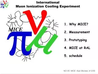
MICE: Muon Ionization Cooling Experiment • MICE Goals: • Design, build, commission, and operate a realistic section of cooling channel • Measure its performance in a variety of modes of operation and beam conditions …results will be used to optimize Neutrino Factory and Muon Collider designs. Spectrometer Solenoid & Tracker RFCC Module Absorber L. Coney – CHEP2012
MICE: Design • MICE is designed to produce a 10% cooling effect on the muon beam • Use particle detectors to measure the cooling effect to 1% • Measurements will be done with muon beams having momentum of 140 MeV/c – 240 MeV/c • Method: • Create beam of muons • Identify muons and reject background • Measure single particle parameters x, px, y, py, pz • Cool muons in absorber • Restore longitudinal momentum component with RF cavities • Identify outgoing particles to reject electrons from muon decay L. Coney – CHEP2012
MICE: Beam Line • Produce p from p interactions with a titanium target • Transport p (Q123) and select momentum (D1) • Collect m (DS) and select momentum (D2) • Transport m to MICE and match to cooling channel • Maximize m purity (reduce p contamination) • Maximize transmission • Define optics for the MICE program LM L. Coney – CHEP2012
Online Group Overview • The MICE Online Group creates, maintains, and ensures proper use of all tools (hardware, software, documentation) within the MLCR (MICE Local Control Room) that allow the experiment to efficiently record high quality data. • We are responsible for: • Controls & Monitoring (C&M) • Data Acquisition (DAQ) • Online Monitoring and Reconstruction • Data Transfer, Networking, and Computing Infrastructure • We also interface closely with systems related to the Online sector including MICE Operations, Offline Software, and Computing. L. Coney – CHEP2012
Online Group Members • Linda Coney (UCR) – head of Online Group • David Colling (Imperial) – head of Software & Computing • Yordan Karadzhov (U. Geneve) – head of DAQ • Pierrick Hanlet (IIT) – head of C&M • Chris Rogers (RAL) – head of Software • Brian Martlew (Daresbury Lab) – C&M • Paul Hodgson (Sheffield U) – C&M (target) • Matt Robinson (Sheffield U) – System Admin; C&M (target, tracker) • Mike Courthold (RAL) – Networking • Henry Nebrensky (Brunel) – GRID, data transfer • Janusz Martynikk (Imperial) – data transfer • Craig Macwaters (RAL) – MLCR Network, hardware, computing • Antony Wilson (RAL) – Config DB, PPD contact • Paul Kyberd (Brunel) – GRID L. Coney – CHEP2012
Outline • Intro – MICE • Muon Ionization Cooling Experiment • Controls & Monitoring • DAQ • Online Monitoring & Reconstruction • Conclusions L. Coney – CHEP2012
MICE: Controls & Monitoring • Controls • User interface to equipment – both beamline and detectors • Mandates proper sequencing • Monitoring • Protects equipment (early notification of problems) & data quality • Required for proper sequencing in Controls • Use EPICS (Experimental Physics & Industrial Control Systems) interface • Framework for C&M • Open source, multiple platforms, stable • Existing support for many devices L. Coney – CHEP2012
C&M: EPICS • Start with hardware and LAN • Use existing drivers or develop new ones • Build Input/Output Controllers (IOCs) which define Process Variables • Make PVs available on LAN for users (clients) or other IOCs • Clients: control or monitoring panels, Alarm Handlers, Archivers L. Coney – CHEP2012
C&M: Status • Completed: All beamline and PID equipment • Target • Beamline magnets • BeamStop, Proton Absorber • Particle ID detectors, Hall environment • Alarm Handler, Archiver • External gateway for remote access L. Coney – CHEP2012
Cooling Channel:Spectrometer Solenoids & Focus Coil • At Wang, NMR (CA) • At TESLA (UK) L. Coney – CHEP2012
SS Standalone System Operational • SS: Quench protection (FNAL), power supply (LBNL), C&M hardware (Daresbury) • FC standalone C&M ready L. Coney – CHEP2012
C&M: Current & Future Focus Spectrometer Solenoid & Tracker RFCC Module Absorber • Config DB: Ensure data taking parameters of all equipment carefully recorded/restored to/from the CDB • Control all systematic errors • Run Control • Target DAQ, Experiment DAQ, beamline controls, MICE state machines, PID • All integrated into single Run Control process • Future: RFCC (RF cavities and coupling coils), further development of infrastructure monitoring (vacuum, compressed air, power, chilled water, etc) L. Coney – CHEP2012
C&M: Run Control • Target Monitoring • Beam Center Distance, ISIS current, Beam Loss due to MICE Target, Beam Position L. Coney – CHEP2012
C&M: Run Control • DAQ Monitoring • Run number • DAQ status • Trigger type • Spill Gate width • Particle triggers • Target info • All information sent to ConfigDB • Continue with State Machines L. Coney – CHEP2012
Outline • Intro – MICE • Muon Ionization Cooling Experiment • Controls & Monitoring • DAQ • Online Monitoring & Reconstruction • Conclusions L. Coney – CHEP2012
MICE Timing • MICE target dips into ISIS beam during last 3 ms of the cycle • MS signal used to time in target with correct pulse • MICE RF will be timed with last 1 ms of ISIS cycle L. Coney – CHEP2012
DAQ & Trigger Requirements • Long-term stability • Maintainable • Non-expert use g documentation • Specifications: • 100s particles/1 ms spill at 1 Hz • Level 0 trigger only – all events read out • Readout at end of spill – buffer in FEE • Dead time not > 1 burst after that which generated particle event • Calibration runs possible between spills • Event size <60 MB (normally ~2 MB; will be ~5 MB with EMR & trackers) L. Coney – CHEP2012
DAQ Software Framework • Using DATE • ALICE DAQ software framework • Provided MICE with EventBuilder tool • Subevents collected by different processors are synchronized and assembled before storage • Version 6.40 g update to v7.34 next month • LDC – Local Data Concentrator • PC connected to the VME crate • Contains set of Equipment • GDC – Global Data Collector • Event builder • Equipment – module in DAQ crate • DATE Event = DAQ Event • Multiple Particle Events (100s) L. Coney – CHEP2012
DAQ Requirements • Flexible: • Performs initialization of FEE units • Read data from FEE through VME bus • Select necessary equipment without modify code • Run independently of target, MICE RF, and individual detectors • Interface with Controls & Monitoring • Interface with Online Monitoring and Reconstruction L. Coney – CHEP2012
DAQ Hardware Overview L. Coney – CHEP2012
DAQ Status • TOF, CKOV, KL completed • Unpacking code finished for all current and future detectors • Prototype EMR detector and electronics successfully integrated • Simultaneous readout of two scintillating fiber trackers with cosmic ray data completed • Successful integration of prototype single station tracker into MLCR DAQ • Timing of tracker alive window and vetos completed • Communication linking DAQ, C&M and Config DB done • Allows DAQ monitoring and archiving of DAQ parameters L. Coney – CHEP2012
Outline • Intro – MICE • Muon Ionization Cooling Experiment • Controls & Monitoring • DAQ • Online Monitoring & Reconstruction • Conclusions L. Coney – CHEP2012
Online Monitoring • Interface is based on DATE monitoring facility • Runs over data on socket • Online monitoring process produces histograms and makes them available on demand • Online Monitoring GUI is just a ROOT macro allowing the user to request histograms • Run unpacker on DATE data • Fill plots for each type of board – no reconstruction • Fill histograms in real time while taking data • Use to debug operations & provides data quality check • Three types of boards g three types of plots • FADCs, Scalar, TDCs L. Coney – CHEP2012
Online Monitoring Trg Req. For cumulative, average and last spill TOF0 CKOVA/B GVA1 Part.Trigger Clock 1MHz GVA3 • Typical online plots during data-taking • User selects what to view • Displayed for each run TOF hit profiles trigger fADC TDC scalars L. Coney – CHEP2012
Online Reconstruction • Unpacker runs over data from DATE on socket • Converts the raw data into information with physical meaning • Real-time physics and detector functionality • First look at analysis quantities • Available now • TOF, CKOV, KL, Sci-Fi Tracker detector readout • Time-of-flight distributions • Beam dynamics • Future: • EMR detector • Additional online analysis L. Coney – CHEP2012
Online Reconstruction Hit Distribution in X Hit Distribution in Y TOF0 TOF0 TOF1 TOF1 Reconstructed Time of Flight m+ p+ e+ • TOF detectors • Shape of beam, particle triggers • CKOV detectors • Time-of-flight distribution • PID L. Coney – CHEP2012
Other • Data transfer • Move data out of MLCR at end of each day and automatically transfer to RAL PPD and GRID for later analysis • Saves associated Online Monitoring and Reconstruction plots with data • Infrastructure • Change in OS in progress, moving from CentOS to SL – using SLv5.7 • Replacement of unreliable DAQ crates completed • Upgrade/replacement of critical machines in progress • Improving equipment protections in case of power outages • Documentation – all has recently been reviewed, updated and posted L. Coney – CHEP2012
Online Future • Prepare complete C&M for arrival of cooling channel elements in 2013 • Spectrometer solenoids, full sci-fi trackers(2), AFC (absorber focus coil) in beam • Move to latest version of DATE • Finish integration of tracker DAQ into MLCR DAQ • Add production versions of EMR equipment to DAQ & take data • Complete timing with ISIS RF and prepare for running with MICE RF • Continue improvement/addition of Online Reconstruction • Add online accelerator physics analysis tools for beam in cooling channel L. Coney – CHEP2012
Conclusions • MICE Online Systems are in place and performing well • Improvements to DAQ, C&M, and Online Reconstruction continue to develop as new requirements arise • Progressing on schedule toward arrival of Cooling Channel elements and subsequent data-taking campaign in 2013 L. Coney – CHEP2012
MICE: International Involvement • Institutions worldwide are contributing to the demonstration of muon ionization cooling at MICE L. Coney – CHEP2012
Online Structure L. Coney – CHEP2012
MICE DAQ Terminology • Isis Cycle: • The injection and acceleration cycle of ISIS. It is 20 ms long (50 Hz). • Machine Start (MS): • This is the pulse used for the ISIS synchronization • Spill Gate: • Time window during which the MICE Target is crossing the ISIS beam. Driven by the cycle of the MICE target. • Burst: • The ~100 ns time window during which muons are in the MICE detectors. Is the time it takes for a proton bunch in ISIS to cross through the MICE target. • DAQ-Trigger: • Signal triggering the readout of the FE-electronics modules of the MICE detectors. One DAQ-Trigger = one DAQ-Event • Particle-Trigger: • Signal generated when the desired Trigger Condition is met. • Distributed to the sub-detectors Front End Electronics and initiates the digitization of the data. L. Coney – CHEP2012
DAQ Trigger Interfacew/Target & Spill Gate • Timing of DAQ with ISIS, Spill Gate, readout • MLCR hardware DAQ Trigger distribution KL TOF & CKOV Shapers GVA Discri, KL cosmics trg Scalars and particle trigger NIM Logic TOF discriminators & trigger CAMAC Logic L. Coney – CHEP2012
TOF FEE • Sensor: PMT (Hamamatsu R4998) • Signal transmission: Single ended, 50 Ohm, coax cable (RG213) • Number of Channels • 40 (TOF0) + 28 (TOF1) + 40 (TOF2) = 108 ch • Main Constraint • Time Resolution • -> Time-walk correction • TDC • CAEN V1290, 32 ch • Large Event Buffer • ECL input • Discriminator • Lecroy 4415 • 16 Channels • ECL output • Twisted Pair Input (110 Ohm) • Need Signal splitting • for charge measurement L. Coney – CHEP2012
KL FEE • Sensor: PMT (Hamamatsu R1355) • Signal transmission: Differential, 120 Ohm, Twisted pair cable • Number of Channels • 42 ch • Main Constraint • Charge measurement • Time ~ 1 ns • Flash ADC (WFD) • CAEN V1724 • 100 MS/s, 14 bits • Best commercial deal • Single Ended, 50 OhmInput L. Coney – CHEP2012
CKOV FEE • Sensor: PMT (8”) • Signal transmission: Single ended, 50 Ohm, coax cable (RG58) • Number of Channels • 4 + 4 = 8 ch • Main Constrain • Rate (no segmentation) • Small charge • Flash ADC (WFD) • CAEN V1731 • 500 MS/s, 8 bits • Single Ended, 50 OhmInput • No Shaper ! L. Coney – CHEP2012
Tracker FEE • Custom Made Digital Data Buffer • VLSB = VME LVDS CERDES Buffer • MICE defined Data format • Measure Both discriminated time and Zero suppressed Charge • 4096 + 4096 = 8198 channels 4 VLSB Boards in VME Crate = Data Buffer 1 Cryo-Cooler = ½ Tracker Read out PC In Control Room Fibers from VLPCs Optical Fiber 4 AFE2-t Boards Digital Signal MIL1553(Control) MICE HALL L. Coney – CHEP2012
DAQ Equipment • Readout code available and tested for • TDC V1290A (TOF) • FADC V1724 (TOF and KL) • FADC V1731 (CKOV and EMR) • Scaler V830 • Trigger Receiver I/O V977 • NI I/O PCi 6254 (Target) • VLSB (Tracker) • Prototype custom EMR Front End Board • Trailer (special equipment handling the release of the busy) L. Coney – CHEP2012