Download
1 / 16
180 likes | 293 Vues
Reservoir Connectivity and Stimulated Gas Flow in Tight Sands “ The Piceance Project”.

E N D
Reservoir Connectivity and Stimulated Gas Flow in Tight Sands“The Piceance Project” It is becoming more important than ever to know the facts and get them out there to avoid derailing the unconventional natural gas industry the way the nuclear energy industry was high-jacked and derailed by misinformation in the late 1970s. Rulison Field, Piceance Basin Tom Davis photo
The Piceance Basin Project Team Ilya Tsvankin, Paul Sava, Andre Revil, Graham Mustoe, John Berger, Bruce Trudgill, Tom Davis, Piret Plink-Bjørklund, Jennifer Aschoff and Dag Nummedal Colorado School of Mines, Golden, CO Matt Pranter and Paul Weimer University of Colorado, Boulder, CO Jim Gilman and Reinaldo Michelena iReservoir.com, Denver, CO Rex Cole Mesa State University, Grand Junction, CO and Many Excellent Students!
Data Donation and Financial Support Bill Barrett Corporation Geology: Image logs (7) through 3000 ft of pay. More that 6000 well logs across the basin Geophysics: 3D multi-component reflection seismic data set (from 2005) for an area of 25.6 mi2. Microseismic data cross-well tomographic data sets. Whiting Petroleum 2D VSP surveys, image logs, and thin sections from 70 rotary sidewall cores from the Boies Ranch field in the northern Piceance basin, for a total value of $319,000. 2D VSP surveys, image logs, and thin sections from 70 rotary sidewall cores Seitel - Regional seismic lines TGS-Nopec, Noble, others – Wireline logs IHS-Petra, Landmark, Schlumberger – Software support Project cost-share consortium members – Antero Resources, Bill Barrett, Antero, Berry Petroleum, ConocoPhillips, EnCana, ExxonMobil, Marathon, Noble Energy, Whiting, Williams
Tectonic Subsidence Across UT-CO Tied to Farallon Slab Migration Farallon plate data from Gurnis’ team
Piceance Basin, Structure • Top Rollins structure map Mike Leibovitz, 2009
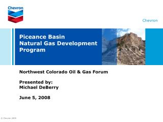
The Major Faults, Fluid Pathways • Ancestral Rockies deformation during Pennsylvanian to Triassic. • Erosion at base Jurassic. Local Pennsylvanian to Triassic missing. • Laramide reactivation of Paleozoic structures at Divide Creek. • Upper Mancos shale is the basal detachment for Wolf Creek Anticline. Wolf Creek Anticline Divide Creek Anticline NW SE Time (Sec. TWTT)
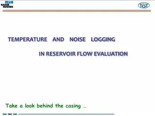
Project From Outcrop to Subsurface 500 1,000 1,500 2,000 2,500 3,000 3,500 4,000 4,500 5,000 5,500 Ft 6248 Wasatch Formation “Ohio Creek Interval” (Dunrud, 1989) Upper Middle Top Cozzette Mbr. Undifferentiated Mancos Parasequences Williams Fork Formation Coal Ridge CZ Upper Ss. Mbr. South Cyn. CZ Lower Middle Ss. Mbr. Cameo-Wheeler CZ Cozzette Mbr. Rollins Ss. Mbr. Iles Fm. Mancos Tongue Cozzette Mbr. Waypoint 028 Mancos Shale Cozzette Mbr. of Iles Fm.
Fracture Analysis and DFN Modeling Fracture Dip Angle and Dip Azimuth Fracture Intensity and Lithology + DFN (discrete fracture network) model Ki Scale up fracture properties Kj Kk
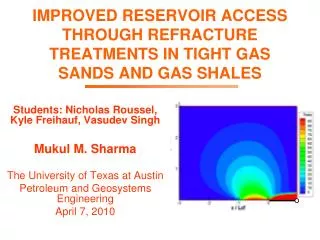
Hydraulic Fracture • Fracture mechanics is traditionally focused on preventing brittle fracture • Oil and natural gas industry began commercially creating and extending fractures to stimulate production in 1949(Howard SPE 1970) • Aims to increase the exposure of the well to the surrounding formation and provide channels for increased production • CHALLENGES(Shlyapobersky et al. SPE 1994) • What fracture mechanisms take place in hydraulic fracturing and how these mechanisms are affected by the rate of injection • How rock heterogeneity (inclusions,micro cracks, formation layers,etc.) affect fracture initiation • How porous properties of rock affect fracture mechanisms
Rock Fracture Modeling OUTPUTS • Effective Mechanical Properties • Material Failure Strengths • Effective Material Strength • Failure Modes • Fracture Initiation • Predictive Tool INPUTS • Material Composition • System Geometry • Constituent Properties • Volume Fractions • Layer Thicknesses • Porosity (void freq. & geometry) • Confining Pressure • Overburden Pressure
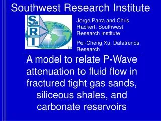
30-Year for Several 25 ft Intervals Zone 1 Big Kahuna Hydraulic Fracture Orientation 30o Paonia Zone 5 Recovery after 30 years, “optimal” hydraulic fractures, 25~30 ft thickness
Some Things We Don’t Know 1. In a recent poll of petroleum engineering professionals, 80% stated that they do not really know where in the reservoir they are actually draining the gas from! This can be viewed as pretty scary, or as a positive indication that there is a lot of upside potential for increased gas production from tight sands. 2. The data in this poll are also pretty consistent with statements from several professionals in the service industry that in many cases more than 80% of the production comes from 20% of the well bore stimulation. This also seems scary, but it is also another indicator of the potential for cost reductions, increased flow, or both. 3. Several sophisticated reservoir modelers in some of the world’s most advanced companies harbor great uncertainties as to whether pore scale flow or fractures control most of the gas flow. High fracture densities actually work against gas production, because the fractures primarily increase water production – not gas. Many big fractures also end up being filled with drilling mud and cement – with big production losses. 4. There are big problems with the concept of “heterogeneity” of reservoirs. The choice of wording sends the message to a wide section of the industry community that the distribution of good quality reservoir rocks and sealing rocks is sort of random. That is not how the sedimentary rock record is built. There is a great deal of order. The very concept behind sequence stratigraphy has articulated this order. Not used much. From CSM workshop, Oct. 22, 2010
Proposed Next RPSEA PhaseSubsurface Characterization Laboratory • Inspired by 1980s MWX experiments • Several closely-spaced wells in Piceance basin – from surface to base Mancos Shale • Drilling, stimulation and completion experiments • Geophysical monitoring (some permanent) • Open first for sponsors (RPSEA, majors and independents) – in the long run for everyone • Major field research site for CSM faculty and students and Colorado partner institutions