Download
1 / 24
240 likes | 272 Vues
Lectures 2 and 3: Gate Delay Ideas Lecture 4: Basic properties of circuit elements Today: Finish up circuit elements How to find delays in circuits which have to charge capacitors (which every circuit effectively has). Review of charging and discharging in RC Circuits. Voltage Source

E N D
Lectures 2 and 3: Gate Delay Ideas Lecture 4: Basic properties of circuit elements Today: Finish up circuit elements How to find delays in circuits which have to charge capacitors (which every circuit effectively has) Review of charging and discharging in RC Circuits
Voltage Source Current Source Resistor Capacitor Inductor (like ideal battery) (always supplies some constant given current) (Ohm’s law) (capacitor law – based on energy storage in electric field of a dielectric) (inductor law – based on energy storage in magnetic field produced by a current BASIC CIRCUIT ELEMENTS
DEFINITION OF IDEAL VOLTAGE SOURCE Symbol Note: Reference direction for voltage source is unassociated (by convention) Examples: 1) V = 3V 2) v = v(t) = 160 cos 377t • Special cases: upper case V constant voltage … called “DC” lower case v general voltage, may vary with time Current through voltage source can take on any value (positive or negative) but not infinite
IDEAL CURRENT SOURCE “Complement” or “dual” of the voltage source: Current though branch is independent of the voltage across the branch + note unassociated v direction Actual current source examples – hard to find except in electronics (transistors, etc.), as we will see upper-case I DC (constant) value lower-case implies current could be time-varying i(t)
Ideal voltage source Assume unassociated signs If V is positive and I is only positive But this is arbitrary; i might be negative so we extend into 2nd quadrant i absorbing power releasingpower V But this is still arbitrary, V could be negative; all four quadrants are possible releasing power absorbing power (charging) CURRENT-VOLTAGE CHARACTERISTICS OF VOLTAGE & CURRENT SOURCES Describe a two-terminal circuit element by plotting current vs. voltage
releasing power absorbing power i V CURRENT-VOLTAGE CHARACTERISTICS OF VOLTAGE & CURRENT SOURCES (con’t) + v _ If i is positive then we are confined to quadrants 4 and 1: Remember the voltage across the current source can be any finite value (not just zero) And do not forget i can be positive or negative. Thus we can be in any quadrant.
Answer: V = 0 I = 0 V = 1V I = 1 mA V = 2V I = 2 mA etc Slope = 1/R RESISTOR If we use associated current and voltage (i.e., i is defined as into + terminal), then v = iR (Ohm’s law) Question: What is the I-V characteristic for a 1K resistor? Note that all wires and circuit connections have resistance, though we will most often approximate it to be zero.
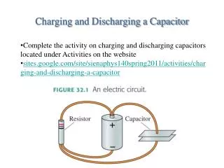
We learned about the parallel-plate capacitor in physics. If the area of the plate is A, the separation d, and the dielectric constant of the insulator is , the capacitance equals C = A /d. Symbol Constitutive relationship: Q = C (Va Vb). (Q is positive on plate a if Va > Vb) CAPACITOR Any two conductors a and b separated by an insulator with a difference in voltage Vab will have an equal and opposite charge on their surfaces whose value is given by Q = CVab, where C is the capacitance of the structure, and the + charge is on the more positive electrode. But so where we use the associated reference directions.
You might think the energy (in Joules) is QV, which has the dimension of joules. But during charging the average voltage was only half the final value of V. Thus, energy is . ENERGY STORED IN A CAPACITOR
ENERGY STORED IN A CAPACITOR (cont.) More rigorous derivation: During charging, the power flow is v i into the capacitor, where i is into + terminal. We integrate the power from t = 0 (v = 0) to t = end (v = V). The integrated power is the energy but dq = C dv. (We are using small q instead of Q to remind us that it is time varying . Most texts use Q.)
INDUCTORS Inductors are the dual of capacitors – they store energy in magnetic fields that are proportional to current. Switching properties: Just as capacitors demand v be continuous (no jumps in V), inductors demand i be continuous (no jumps in i ). Reason? In both cases the continuity follows from non-infinite, i.e., finite, power flow.
SWITCHING PROPERTIES OF L, C Rule: The voltage across a capacitor must be continuous and differentiable. For an inductor the current must be continuous and differentiable. Basis: The energy cannot “jump” because that would require infinite energy flow (power) and of course neither the current or voltage can be infinite. For a capacitor this demands that V be continuous (no jumps in V); for an inductor it demands i be continuous (no jumps in i ).
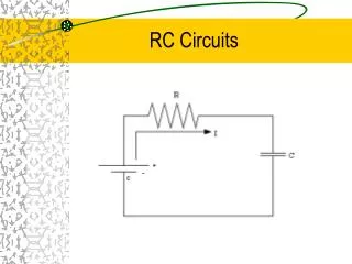
R represents total resistance (wire plus whatever drives the input) The RC Circuit to Study(All single-capacitor circuits reduce to this one) • C represents the total capacitance from node to the outside world (from devices, nearby wires, ground etc)
Vin R Input node Output node Vout + C Vin 0 time - 0 ground 5 Time period during which the output changes: transient Vout 0 time 0 RC RESPONSE EXAMPLE Case 1 Capacitor uncharged: Apply + voltage step of 2V 5 The capacitor voltage, Vout, is initially zero and rises in response to the step in input. Its initial value, just after the step, is still zero WHY? Its final value, long after the step is is 5V WHY? We need to find the solution during the transient.
V1 Vin R Input node Output node Vout + Vout C Vin 0 time - 0 ground RC RESPONSE Case 1 – Rising voltage. Capacitor uncharged: Apply + voltage step • Vin “jumps” at t=0, but Vout cannot “jump” like Vin. Why not? • Because an instantaneous change in a capacitor voltage would require instantaneous increase in energy stored (1/2CV²), that is, infinite power. (Mathematically, V must be differentiable: I=CdV/dt) V does not “jump” at t=0 , i.e. V(t=0+) = V(t=0-) Therefore the dc solution before the transient tells us the capacitor voltage at the beginning of the transient.
V1 Vin R Input node Output node Vout + Vout C Vin 0 time - 0 ground RC RESPONSE Case 1 – Capacitor uncharged: Apply voltage step • Vout approaches its final value asymptotically (It never quite gets to V1, but it gets arbitrarily close). Why? • After the transient is over (nothing changing anymore) it means d(V)/dt = 0 ; that is all currents must be zero. From Ohm’s law, the voltage across R must be zero, i.e. Vin = Vout. • That is, Vout V1 as t . (Asymptotic behavior) Again the dc solution (after the transient) tells us (the asymptotic limit of) the capacitor voltage during the transient.
R Input node Output node Vout + C Vin - ground V1 Vout t time 0 0 RC RESPONSE: Case 1 (cont.) Vout ? Equation for Vout: Do you remember general form? Exact form of Vout? Vout = V1(1-e-t/t) Exponential!
at t = 0, Vout = 0 , and at t , Vout V1 also at t = t, Vout = 0.63 V1 at t = 0, Vout = V1 , and at t , Vout 0, also at t = t, Vout = 0.37 V1 8 8 Vout Vout V1 V1 .63V1 .37V1 0 0 time 0 time t 0 t Review of simple exponentials. Rising Exponential from Zero Falling Exponential to Zero Vout = V1(1-e-t/t) Vout = V1e-t/t
Vout Vout V1 + V2 V1 + V2 .63V1+ V2 .37V1 + V2 V2 V2 0 time 0 t 0 time 0 t Further Review of simple exponentials. Rising Exponential from Zero Falling Exponential to Zero Vout = V1(1-e-t/t) Vout = V1e-t/t We can add a constant (positive or negative) Vout = V1(1-e-t/t) + V2 Vout = V1e-t/t + V2
Vout = A + Be-t/t Vout Vout A A+B Here B > 0 Here B < 0 A+B A 0 0 time 0 time 0 Further Review of simple exponentials. Rising Exponential Falling Exponential Vout = V1e-t/t + V2 Vout = V1(1-e-t/t) + V2 Both equations can be written in one simple form: Initial value (t=0) : Vout = A + B. Final value (t>>t): Vout = A Thus: if B < 0, rising exponential; if B > 0, falling exponential
RC RESPONSE: Proof RC is “time constant” t ! Large R or large C => slow rise and fall
RC RESPONSE: Proof We know Vout(t) = Vin + [Vout(t=0)-Vin]e-t/RC Is a solution? Substitute:
R Input node Output node Vout + Vin C - ground Vin 10 Vout 6.3V DRAW THE GRAPH 0 time 0 1nsec Example The simple RC circuit with a step input has a universal exponential solution of the form: Vout = A + Be-t/RC Example: R = 1K, C = 1pF, Vin steps from zero to 10V at t=0: • Initial value of Vout is 0 • Final value of Vout is 10V • Time constant is 10-9 sec • Vout reaches 0.63 X 10 in 10-9 sec Vout = 10 - 10e-t/1nsec Now just write the equation:
R Input node Output node Vout + C Vin - ground Charging and discharging in RC Circuits(The official EE40 Easy Method) Method of solving for any node voltage in a single capacitor circuit. 1) Simplify the circuit so it looks like one resistor, a source, and a capacitor (it will take another two weeks to learn all the tricks to do this.) But then the circuit looks like this: 2) The time constant of the transient is t = RC. 3) Solve the dc problem for the capacitor voltage before the transient. This is the starting value (initial value) for the transient voltage. 4) Solve the dc problem for the capacitor voltage after the transient is over. This is the asymptotic value. 5) Sketch the Transient. It is 63% complete after one time constant. 6) Write the equation by inspection.