Download
1 / 42
420 likes | 504 Vues
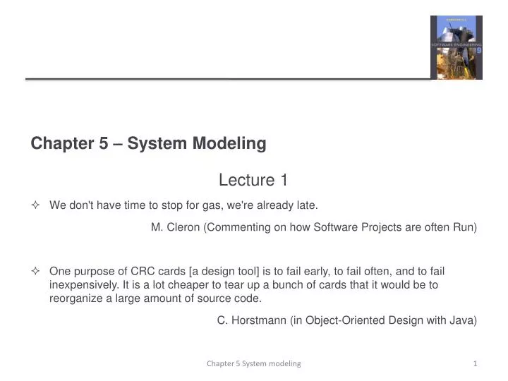
Chapter 5 – System Modeling. Lecture 1 We don't have time to stop for gas, we're already late. M. Cleron (Commenting on how Software Projects are often Run)

E N D
Chapter 5 – System Modeling Lecture 1 • We don't have time to stop for gas, we're already late. M. Cleron (Commenting on how Software Projects are often Run) • One purpose of CRC cards [a design tool] is to fail early, to fail often, and to fail inexpensively. It is a lot cheaper to tear up a bunch of cards that it would be to reorganize a large amount of source code. C. Horstmann (in Object-Oriented Design with Java) Chapter 5 System modeling
Topics covered • Overview • Context models • Interaction models • Structural models • Behavioral models • Model-driven engineering Chapter 5 System modeling
System modeling • System modeling • the process of developing abstract models of a system, • each model presents a different view/perspective of the system. • System modeling techniques • representing a system using some kind of graphical notation, • now almost always based on notations in the Unified Modeling Language (UML). • System modelling goals • help understand the functionality of the system • models are used to communicate with customers. Chapter 5 System modeling
Existing and planned system models • Models of the existing system are used during requirements engineering. • They help clarify what the existing system does and can be used as a basis for discussing its strengths and weaknesses. • These then lead to requirements for the new system. • Models of the new system are used during requirements engineering to help explain the proposed requirements to other system stakeholders. • Engineers use these models to discuss design proposals and to document the system for implementation. • In a model-driven engineering process, it is possible to generate a complete or partial system implementation from the system model. Chapter 5 System modeling
System perspectives • An external perspective, where you model the context or environment of the system. • An interaction perspective, where you model the interactions between a system and its environment, or between the components of a system. • A structural perspective, where you model the organization of a system or the structure of the data that is processed by the system. • A behavioral perspective, where you model the dynamic behavior of the system and how it responds to events. Chapter 5 System modeling
UML diagram types • Activity diagrams, which show the activities involved in a process or in data processing . • Use case diagrams, which show the interactions between a system and its environment. • Sequence diagrams, which show interactions between actors and the system and between system components. • Class diagrams, which show the object classes in the system and the associations between these classes. • State diagrams, which show how the system reacts to internal and external events. Chapter 5 System modeling
Use of graphical models • As a means of facilitating discussion about an existing or proposed system • Incomplete and incorrect models are OK as their role is to support discussion. • As a way of documenting an existing system • Models should be an accurate representation of the system but need not be complete. • As a detailed system description that can be used to generate a system implementation • Models have to be both correct and complete. Chapter 5 System modeling
Topics covered • Context models • Interaction models • Structural models • Behavioral models • Model-driven engineering Chapter 5 System modeling
Context models are used to illustrate the operational context of a system - they show what lies outside the system boundaries. Social and organisational concerns may affect the decision on where to position system boundaries. Architectural models show the system and its relationship with other systems. Context models Chapter 5 System modeling
System boundaries • System boundaries are established to define what is inside and what is outside the system. • They show other systems that are used or depend on the system being developed. • The position of the system boundary has a profound effect on the system requirements. • Defining a system boundary is a political judgment • There may be pressures to develop system boundaries that increase / decrease the influence or workload of different parts of an organization. Chapter 5 System modeling
The context of the MHC-PMS Chapter 5 System modeling
Process perspective • Context models • show the other systems in the environment, not how the system being developed is used in that environment. • Process models • reveal how the system being developed is used in broader business processes. • Technique • UML activity diagrams may be used to define business process models. Chapter 5 System modeling
Process model of involuntary detention Chapter 5 System modeling
Topics covered • Context models • Interaction models • Structural models • Behavioral models • Model-driven engineering Chapter 5 System modeling
Interaction models • user interaction • identify user requirements. • system-to-system interaction • highlights the communication problems that may arise. • component interaction • helps us understand if a proposed system structure is likely to deliver the required system performance and dependability. • Technique • Use case diagrams and sequence diagrams may be used for interaction modelling. Chapter 5 System modeling
Use case modeling • Use cases • developed originally to support requirements elicitation • now incorporated into the UML. • Each use case represents a discrete task that involves external interaction with a system. • Actors in a use case may be people or other systems. • Technique • diagrams provide an overview of the use case • textual form provides details Chapter 5 System modeling
Transfer-data use case • A use case in the MHC-PMS Chapter 5 System modeling
Tabular description of the ‘Transfer data’ use-case Chapter 5 System modeling
Use cases in the MHC-PMS involving the role ‘Medical Receptionist’ Chapter 5 System modeling
Sequence diagrams • Sequence diagrams • part of the UML • used to model the interactions between the actors and the objects within a system. • Goal • A sequence diagram shows the sequence of interactions that take place during a particular use case or use case instance. • Technique • The objects and actors involved are listed along the top of the diagram, with a dotted line drawn vertically from these. • Interactions between objects are indicated by annotated arrows. Chapter 5 System modeling
Objects are laid out left to right at the top of the diagram The object’s “lifeline” is represented by a dashed line extending down from the object Along the lifeline are narrow rectangles representing the object’s activation Represents an execution of an operation carried out by the object Length signifies the activation’s duration UML notation
A message that goes from one object to another is represented by a solid arrow going from the first object’s lifeline to the second. An object can send a message to itself UML notation for sequence diagrams object1 object2
Simple Transfer of control from one object to another Synchronous If an object sends a synchronous message, it waits for a response (return value) before proceeding Asynchronous Object does not wait for a response (return value) Messages
:FrontPanel :Register :Dispenser Insert($) validateAmount($, S) Select(S) dispense(S) Deliver(S) Successful buy soda scenario
Check out resource scenario sequence diagram :Patron :Book :LibraryDB :LibrarySystem getResource(RID) getPatron(PID) create() validatePatron(PID) create() checkOut(RID) checkOut(PID) Update() Update()
Sequence diagram for View patient information Chapter 5 System modeling
Sequence diagram for Transfer Data Chapter 5 System modeling
Topics covered • Context models • Interaction models • Structural models • Behavioral models • Model-driven engineering Chapter 5 System modeling
Structural models • Structural models of software display the organization of a system in terms of the components that make up that system and their relationships. • Types of Structural models • static models, which show the structure of the system design • dynamic models, which show the organization of the system when it is executing. • You create structural models of a system when you are discussing and designing the system architecture. Chapter 5 System modeling
Class diagrams • Class diagrams are used when developing an object-oriented system model to show the classes in a system and the associations between these classes. • An object class can be thought of as a general definition of one kind of system object. • An association is a link between classes that indicates that there is some relationship between these classes. • When you are developing models during the early stages of the software engineering process, objects represent something in the real world, such as a patient, a prescription, doctor, etc. Chapter 5 System modeling
UML classes and association Chapter 5 System modeling
Classes and associations in the MHC-PMS Chapter 5 System modeling
The Consultation class • The upper part holds the name of the class • The middle part contains the attributes of the class • The bottom part gives the methods or operations the class can take or undertake Chapter 5 System modeling
Associations • An association represents a family of links. • Binary associations (with two ends) are normally represented as a line. • An association can be named, • the ends of an association can be adorned with role names, ownership indicators, multiplicity, visibility, and other properties. • There are four different types of association: • bi-directional, • uni-directional, • Aggregation (includes Composition aggregation) and • Reflexive. Bi-directional and uni-directional associations are the most common. Chapter 5 System modeling
Associations: uni-directional In generic terms, the causation is usually called "sending a message", "invoking a method" or "calling a member function" to the controlled object. Concrete implementation usually requires the requesting object to invoke a method or member function using a reference or pointer to the memory location of the controlled object. Chapter 5 System modeling
Association: bi-directional 0..1 No instances, or one instance (optional, may) 1 Exactly one instance 0..* or * Zero or more instances 1..* One or more instances (at least one) This example is bi-directional. A Person may subscribe to many Magazines A Magazine may have many subscribers Chapter 5 System modeling
Associations: Aggregation • Aggregation is a variant of the "has a" or association relationship; • aggregation is more specific than association. • It is an association that represents a part-whole or part-of relationship. • an aggregation may not involve more than two classes. Chapter 5 System modeling
Associations: Aggregation In UML, it is graphically represented as a hollow diamond shape on the containing class end of the tree with a single line that connects the contained class to the containing class. The aggregate is semantically an extended object that is treated as a unit in many operations, although physically it is made of several lesser objects. Chapter 5 System modeling
Associations: Aggregation Chapter 5 System modeling
Association: Composition • Composition is a stronger variant of the "owns a" or association relationship; • composition is more specific than aggregation. • Composition usually has a strong life cycle dependency between instances of the container class and instances of the contained class(es): • If the container is destroyed, normally every instance that it contains is destroyed as well Chapter 5 System modeling
Associations: Composition The UML graphical representation of a composition relationship is a filled diamond shape on the containing class end of the tree of lines that connect contained class(es) to the containing class. Chapter 5 System modeling
Key points • A model is an abstract view of a system that ignores system details. Complementary system models can be developed to show the system’s context, interactions, structure and behavior. • Context models show how a system that is being modeled is positioned in an environment with other systems and processes. • Use case diagrams and sequence diagrams are used to describe the interactions between users and systems in the system being designed. Use cases describe interactions between a system and external actors; sequence diagrams add more information to these by showing interactions between system objects. • Structural models show the organization and architecture of a system. Class diagrams are used to define the static structure of classes in a system and their associations. Chapter 5 System modeling