Download
1 / 21
230 likes | 488 Vues
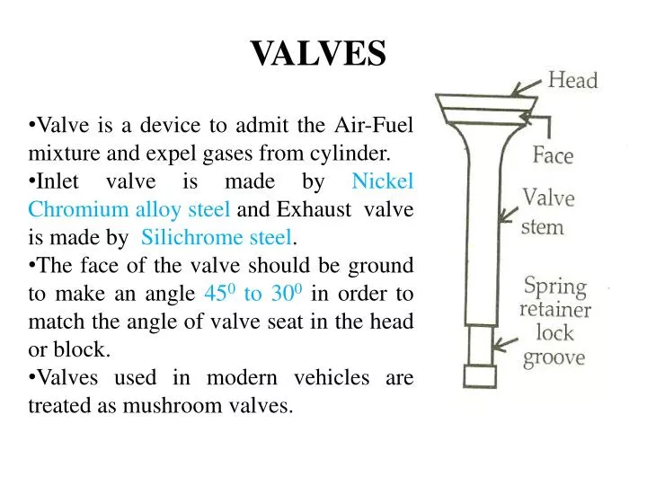
VALVES. Valve is a device to admit the Air-Fuel mixture and expel gases from cylinder. Inlet valve is made by Nickel Chromium alloy steel and Exhaust valve is made by Silichrome steel .

E N D
VALVES • Valve is a device to admit the Air-Fuel mixture and expel gases from cylinder. • Inlet valve is made by Nickel Chromium alloy steel and Exhaust valve is made by Silichrome steel. • The face of the valve should be ground to make an angle 450 to 300in order to match the angle of valve seat in the head or block. • Valves used in modern vehicles are treated as mushroom valves.
1290 degrees F (typical)
Exhaust valves are often filled with metallic sodium for cooling. • Valve faces may be coated with Stellite to reduce wear and corrosion.
Camshaft • Turns at 1/2 the speed of the crankshaft • Must be mechanically coupled to the crankshaft for timing purposes (gears, belts, chains) • The camshaft consists of bearing journals and lobes spaced along the shaft • Each lobe is positioned to open and close a valve at a specific time Lobe
Pushrod • Transmits push of lifter up to rocker arm • Hollow to allow oil to flow to the top of the cylinder for valve part lubrication • Length can be varied to adjust valve clearance • Valve clearance is the space between the top of the valve stem and the rocker arm. This clearance is to prevent a valve from being held open with the resulting heat build-up and loss of compression
Valve Springs • Inner and outer springs are used to prevent bounce, to provide redundancy and increase the valve closing pressure • Held in place by retainer washers on the top and bottom of the spring • Split key or “keeper” holds the retainers and springs in place on the valve stem
Valve Lifter or Tappet • May be solid, roller, or hydraulic • The lifter follows the cam lobes and pushes on the pushrod • Solid and roller lifters require adjustable rocker arms • Hydraulic type lifters fill with oil and lengthened to compensate for any clearances in the valve system
Rocker Arm • Adjustable in solid lifter engines and fixed in engines with hydraulic lifters • One end rests on the valve stem and the other on the pushrod • Rocking motion opens and closes the valves • Roller rocker arms incorporate a roller that reduces friction and are used in some radials and experimental engines
There are two types of valve actuating mechanisms namely • Overhead mushroom valve mechanism and • Straight mushroom valve mechanism
Valve clearance adjustment Valve clearance measurement
Valve Timing diagram Valve Overlap EVC IVO IVC EVO
To see how valve-timing works in a 4-stroke engine cycle, let’s show piston motion as a circle. In this simple cycle, each stroke is shown as a semi-circle. • The intake valve opens at top dead center, and closes at bottom dead center. The blue line shows that period and it matches the intake stroke. • The exhaust valve opens at bottom dead center, then closes at top dead center before the new air-fuel mixture enters the cylinder. • In practice, the intake valve usually opens earlier than top dead center, and stays open a little past bottom dead center. • The exhaust valve opens a little before bottom dead center, and stays open a little past top dead center. • When the valves actually open and close, can be measured by angles. To make these angles easier to read, let’s use a spiral instead of a circle.
This intake valve opens 12° before the piston reaches top dead center. • And it closes 40° after bottom dead center. • The exhaust valve opens 47° before bottom dead center - and stays open - until 21° past top dead center. This gives exhaust gases more time to leave. • By the time the piston is at 47° before bottom dead center on the power stroke, combustion pressures have dropped considerably and little power is lost by letting the exhaust gases have more time to exit. • When an intake valve opens before top dead center and the exhaust valve opens before bottom dead center, it is called LEAD. • When an intake valve closes after bottom dead center, and the exhaust valve closes after top dead center, it is called lag. • On the exhaust stroke, the intake and exhaust valve are open at the same time for a few degrees around top dead center. This is called Valve Overlap. • Different engines use different timings. Manufacturer specifications contain the exact information.
Port Timing Diagram (TDC) EPO EPC IPC IPO (BDC)
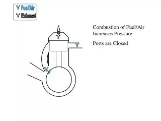
Exhaust Port opens before piston reaches BDC and after sometime inlet valve opens. During next stroke of the piston, first inlet valve closes then exhaust valve closes. After exhaust port closes compression of fuel-air mixture takes place