Download
1 / 24
240 likes | 252 Vues
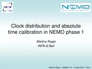
Time calibration in NEMO. M. Circella, INFN Bari. Time calibration The NEMO Phase 1&2 towers Time calibration in NEMO Phase 1: approach, implementation, results Time calibration in NEMO Phase 2. FCM Symmetric systems offshore and onshore

E N D
Time calibration in NEMO M. Circella, INFN Bari Time calibration The NEMO Phase 1&2 towers Time calibration in NEMO Phase 1: approach, implementation, results Time calibration in NEMO Phase 2
FCM Symmetric systems offshore and onshore Dense Wavelength Division Multiplexing (DWDM) based on passive Add&Drop Synchronous Protocol FCM onshore offshore Clock recovered offshore from data flow OM Front End (FE) and time-stamping in OM Analog signals sampled at fixed rate (200 MHz) Data recording triggered when signal exceeds a remotely-setthreshold The clock recovered by FCM is sent to OM Synchronous Protocol FCM OM NEMO Phase 1 mini-tower Floor Control Module (FCM) Optical Module (OM & FE) Synchronous protocol 220 m 40 m DWDM Add&Drop 800 Mbps Synchronous protocol 100 m Junction Box
TDC 25ps sensitive GPS receiver (+/-30 ns RMS) GPS Antenna (now on the roof ot the onshore station) Control PC Modular Crate with FPGA board by National Instr. Clock Shore Station • Clock recovery from GPS receiver • Data and time recovery from GPS by IRIG-B format • Clock Fan-out toward onshore-FCMs • UTC data flow sent to onshore FCMs in synchronous protocol • Go-and-Back time measurements between each pair of onshore/offshore FCMs by TDC • Network Time Protocol (NTP) server for synchronization of PCs by ethernet NTP GPS Antenna RS232 GPS Receiver PC IRIG-B Clock 10MHz Startx TDC SCSI Connecting Board FPGA Stopx 4 X LVDS Time Data 4Mbit/s 4 X LVDS Clock 4MHz
Time measurements in NEMO • Time stamping is made by means of a 16-bit counter incremented at 100 MHz inside each OM • PMT waveforms are sampled at 200 MHz • All offshore clocks are synchronized to the onshore (GPS-syncronized) clock • Time is measured in units of 125 s • Each OM can be considered as a clock which measures time correctly but with a fixed delay w.r.t. to the onshore clock
We need a system able to illuminate the PMTs at known times Time measurements in NEMO (and time calibration) • Each OM can be considered as a clock which measures time correctly but with a fixed delay w.r.t. to the onshore clock • Such delay depends on: • - length of cables (fixed once the integration is finished) • - onshore and offshore electronics (fixed but… ageing may matter?) • - PMT transit time (it depends on the operating conditions and may change with ageing)
Optical module Optical fibre (in connection cables) Electro-optical connector pulser splitting box Time calibration system of NEMO Phase 1 IV floor III floor II floor Approach: network of optical fibres to illuminate groups of PMTs by means of fast optical pulsers I floor
Whyanoptical fibre network fortimecalibration (in Phase 1)? • We decided not to use optical beacons in the water, because of: • Large spacing (and peculiar orientation) of the PMTs on the NEMO tower • Decoupling from positioning system and water characteristics (e.g.: attenuation, scattering) • With a proper design of the fibre network, the PTMs can be illuminated at comparable levels of light • Interesting possibility for the implementation of very large detectors
The search has been made with attention to the best optical properties (attenuation, chromatic and multimodal dispersion) The fibre was then characterized for the effects on operating conditions (temperature, pressure) The optical fibre • Monomodal and multimodal fibres tested • Optimal fibre features: • multimodal • low chromatic dispersion at visible wavelengths • large numerical aperture • large core • Selected fiber: Thorlabs AFS50/125 • Multimode 0.22 NA • Core 50 m
Testing/characterizing the fibre Oven tests: negligible temperature correction needed for our fibre lengths Hyperbaric tests: no performance variation up to 200 bar
Commercial components (cheap and easily available) used for splitter box assembly Electro-optical connector Splitter 10/90 1x2 Splitter 50/50 1x2 Splitter 50/50 2x2 The optical network
Small and compact board Evolved from an old design by Kapustinski et al. Response time jitter less than 100 ps Coarse and fine control of the pulse intensity Pulse intensity may be changed from 1-2 to about 10 photoelectrons No performance degradation after (equivalent) usage of >5 years The optical pulser Intensity control Power connector Pulser Power conditioning LED + fibre interface Control connector • LED Agilent HLMP CB15 InGaN Blue • Central wavelength 472 nm • Low power consumption (+5V e +12V)
We need effective and robust coupling A collimator is used on the pulser board for LED/optical fibre coupling Optical interfaces I
We need effective and robust coupling A collimator is used on the pulser board for LED/optical fibre coupling The light is injected into the PMT from its neck 10° Optical interfaces II
Putting all things together… 160 cm 70 cm Floor Control Module (internal view) Floor Control Module (external view)
Putting all things together…(II) Various phases of FCM integration
(Raw) signals from the optical pulsers Example: the pulser from plane 2 illuminates the OMs on planes 1, 2 and 3 Low-resolutioncalibrationpulsetimes OM0 and OM3 on plane 1 The four OMs on plane 2 OM0 and OM3 on plane 3
Control Panel Result Panel OFFSET INTERFACE
Offseti= 125 s – t peak,i + pre-calibrationi Offset calculations High-resolution correction Time in 125µs time window
System worked smoothly in NEMO Phase 1, but… pre-calibration was a hard task cabling layout was complicated (and integration of FCM painful) fibres increase cable costs No calibration fibres in NEMO Phase 2 cables Optical pulsers moved into the optical modules From Phase 1 to Phase 2
TimCal: - it generates the calibration pulses - it controls the pulse intensity - it generates ‘echo’ signals TimCtrl: - it communicates with the shore station - it takes control of TimCal operations - it performs TDC measurements of the echo signals from TimCal The NEMO Phase 2 time cal. system Upper floor TimCal TimCal TimCal TimCal • Requirements: • - TimCal stable for an adequate lifetime • - Cable delays are known (or measurable) FCM 2 pairs TimCtrl 1 pair 1 pair clock out in FCM Lower floor • Power of TimCal transferred from TimCtrl • Power of TimCtrl & TimCal: +12V
TimCal: equipped with an Altera MAX-II CPLD for all logic operations 2 DACs used or LED voltage set (coarse/fine resolution) ADC for voltage check LED support redesigned The NEMO Phase 2 time cal. system Upper floor TimCal TimCal TimCal TimCal FCM 2 pairs TimCtrl 1 pair 1 pair clock out in FCM Lower floor TimCal board (prel.)
The NEMO Phase 2 time cal. system • The pulser will be mounted directly on the front-end board • The light will be injected into the PMT by means of an optical fibre using the same interface used in Phase 1
TimCtrl: Commercial board (featuring Altera Cyclone III FPGA) + connection board TDC implemented inside FPGA (resolution ~0.5 ns) The NEMO Phase 2 time cal. system Upper floor TimCal TimCal TimCal TimCal TimCtrl board FCM 2 pairs TimCtrl 1 pair 1 pair clock out in FCM Lower floor Connection board (prel.)
Conclusions • Time calibration system of NEMO Phase 1 up and running… • Time calibration system of NEMO Phase 2 under implementation • Both systems may be useful developments for very large detectors