Download
1 / 52
560 likes | 871 Vues
CONTROL SYSTEM. BTRA. CONTROL SYSTEM SCHEMATIC. Schematic of TCU(TCM) control system. The electronic control system is comprised of sensors, a TCU and seven solenoids. The TCU reads the inputs, and under software control activates the outputs according to values

E N D
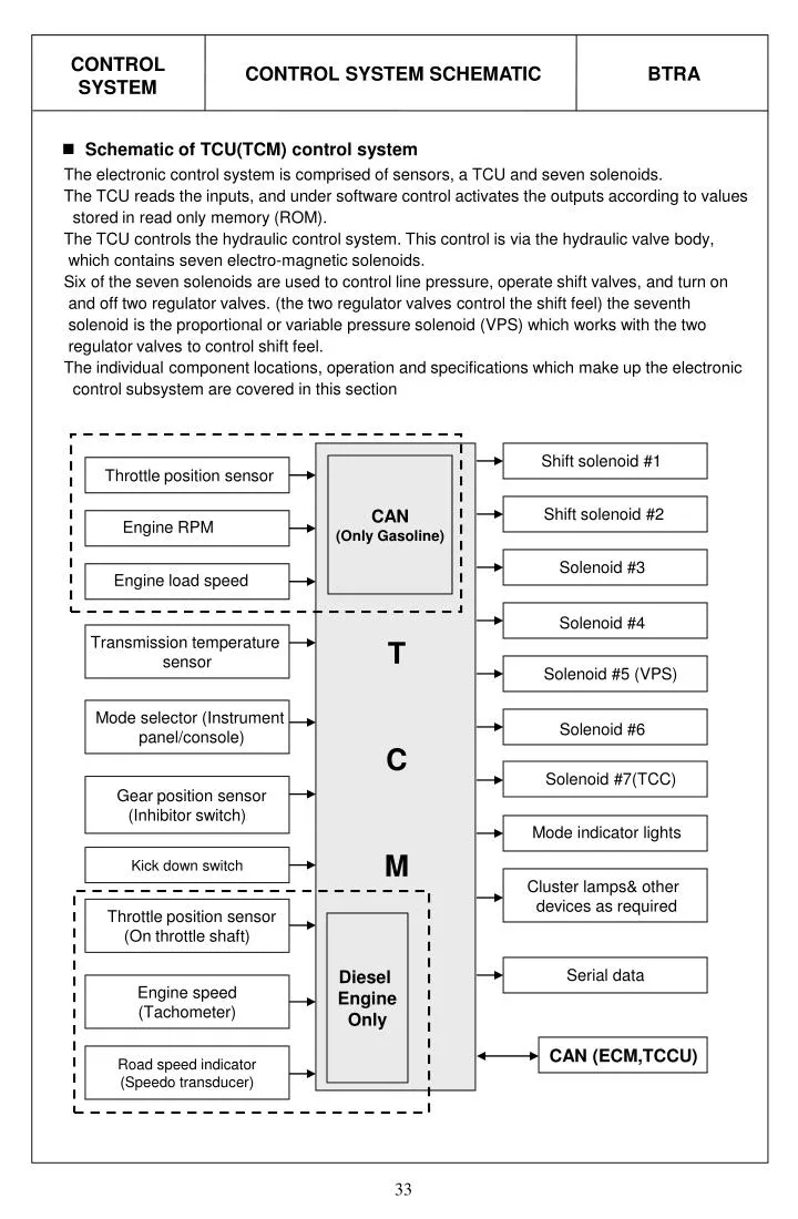
CONTROL SYSTEM BTRA CONTROL SYSTEM SCHEMATIC • Schematic of TCU(TCM) control system The electronic control system is comprised of sensors, a TCU and seven solenoids. The TCU reads the inputs, and under software control activates the outputs according to values stored in read only memory (ROM). The TCU controls the hydraulic control system. This control is via the hydraulic valve body, which contains seven electro-magnetic solenoids. Six of the seven solenoids are used to control line pressure, operate shift valves, and turn on and off two regulator valves. (the two regulator valves control the shift feel) the seventh solenoid is the proportional or variable pressure solenoid (VPS) which works with the two regulator valves to control shift feel. The individual component locations, operation and specifications which make up the electronic control subsystem are covered in this section Shift solenoid #1 CAN (Only Gasoline) Throttle position sensor Shift solenoid #2 Engine RPM Solenoid #3 Engine load speed Solenoid #4 Transmission temperature sensor T C M Solenoid #5 (VPS) Mode selector (Instrument panel/console) Solenoid #6 Solenoid #7(TCC) Gear position sensor (Inhibitor switch) Mode indicator lights Kick down switch Cluster lamps& other devices as required Throttle position sensor (On throttle shaft) Diesel Engine Only Serial data Engine speed (Tachometer) CAN (ECM,TCCU) Road speed indicator (Speedo transducer)
CONTROL SYSTEM BTRA TRANSMISSION CONTROL UNIT • Transmission control unit (TCU) The TCU is an in-vehicle micro-processor based transmission management system. It is usually mounted in the vehicle cabin, under the instrument panel, under the seat, behind the side kick panels or under the floor in the foot well on the passenger side. Different control units are supplied for different vehicle applications. The TCU contains: w Processing logic circuits which include a central micro-controller and a back-up memory system. w Input circuits. w Output circuits which control external devices such as the variable pressure solenoid (VPS), on/off solenoid drivers, a diagnostics output and the driving mode indicator light. The various items which make up the TCU are discussed below. Processing Logic Shift schedule and calibration information is stored in an erasable programmable read only memory (EPROM). Throttle input calibration constants and the diagnostics information are stored in electrically erasable programmable read only memory (EEPROM) that retains the memory even when power to the TCU is disconnected. In operation the software continuously monitors the input values and uses these, via the shift schedule, to determine the required gear state. At the same time it monitors, via the solenoid out puts, the current gear state. Whenever the input conditions change such that the required gear state is different to the current gear state, the TCU initiates a gear shift to bring the two states back into line. Once the TCU has determined the type of gearshift required the software accesses the shift logic, estimates the engine torque output, adjusts the variable pressure solenoid ramp pressure then executes the shift. The TCU continuously monitors every input and output circuit for short or open circuits and operating range. When a failure or abnormal operation is detected the TCU records the condition code in the diagnostics memory and implements a limp mode, The actual limp mode used depends upon the failure detected with the object to maintain maximum driveability without damaging the transmission. In general input failures are handled by providing a default value. Output failures, which are capable of damaging the transmission, result in full limp mode giving only third or fourth gear and reverse. The TCU is designed to operate at ambient temperatures between -40 and 85°C . It is also protected against electrical noise and voltage spikes, however all the usual precautions should be observed, for example when arc welding or jump starting.
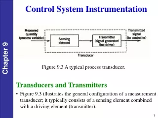
CONTROL SYSTEM BTRA TRANSMISSION CONTROL UNIT • Input factor of Transmission control unit (TCU) To function correctly, the TCU requires engine speed, road speed, transmission sump temperature, throttle position and gear position inputs to determine the variable pressure solenoid current ramp and on/off solenoid states. This ensures the correct gear selection and shift feel for all driving conditions. The inputs required by the TCU are as follows: w Engine Speed The engine speed signal is derived from the tachometer signal line, a dedicated sensor or a Controlled Area Network (CAN). w Road Speed 4WD (Diesel) - The shaft speed signal is derived from the speed sensor located on the transfer case. This signal is transmitted directly to the TCU. 4WD (Gasoline) - The speed sensor sends the shaft speed signal to the engine control module (ECM). The information is then transferred to the TCU via the CAN. w Transmission Sump Temperature The transmission sump temperature sensor is a thermister located in the solenoid wiring tube within the transmission. This sensor is a typical NTC resistor with low temperatures producing a high resistance and high temperatures producing a low resistance. Temperature/Resistance characteristics and location within the solenoid wiring harness tube are shown as follow figures : (Temperature Sensor Location in Solenoid Loom)
CONTROL SYSTEM TRANSMISSION TEMPERATURE SENSOR BTRA • Transmission temperature sensor The transmission sump temperature sensor is a thermistor located in the solenoid wiring harness tube in the transmission oil pan side. This sensor is a typical NTC resistor with low temperatures producing a high resistance and high temperatures producing a low resistance. If the transmission sump temperature exceeds135℃, the TCU will impose converter lock-up at lower vehicle speed and the vehicle flashes the mode indicator lamp. This results in maximum oil flow through the external oil cooler and eliminates slippage in the torque converter. Both these actions combine to reduce the oil temperature in the transmission. Resistance(㏀) Temperature(℃)
THROTTLE POSITION SENSOR (ONLY 4WD DIESEL) CONTROL SYSTEM BTRA • Throttle position sensor The throttle position sensor (TPS) is a resistance potentiometer mounted on the throttle body of the engine. It transmits a signal to the TCU proportional to the throttle plate opening. The potentiometer is connected to the TCU by three wires: 5 volts positive supply, earth and variable wiper voltage. Throttle voltage adjustments are as follows: w closed throttle voltage is 0.5 to 1.0V w wide open throttle voltage is 3- 4.5V These measurements are taken terminal between pin 29(A16) and 27(A18) of the TCU(TCM) terminal. Maintaining good shift feel through the transmission life span is dependant on having an accurate measure of the engine throttle position. To achieve this the TCU continuously monitors the maximum and minimum throttle potentiometer voltages values. However these limits will be lost and will require relearning should a new TCU be installed, or the throttle calibration data is cleared by the execution of a particular sequence. This last instance depends on the installation, and reference should be made to the diagnostics section of this. The relearning will happen automatically. • Throttle position adjustment specification
GEAR POSITION SENSOR / INHIBITOR SWITCH CONTROL SYSTEM BTRA • Gear position sensor and Inhibitor switch The gear position sensor is incorporated in the inhibitor switch mounted on the side of the transmission case. The gear position sensor is a multi-function switch providing three functions: w inhibit starting of the vehicle when the shift lever is in a position other than Park or Neutral w illuminate the reverse lamps when Reverse is selected w indicate to the TCU which lever position has been selected by way of a varying resistance. Gear Position Sensor (2 pins) Inhibitor Switch (4 pins) • Shift lever rod adjustment 30 mm 1) Select shift lever to “D” position. 2) loosen the inhibitor switch adjust nut. 3) Place the inhibitor switch lever to “D”. 4) Tighten the adjust nut,and check the connection condition of inhibitor switch “A” and “B” when the “P” or “ N” is selected. 5) The engine should start at “P” and “N” position. Shift lever rod Inhibitor link
DIAGNOSTIC INPUT / BATTERY VOTAGE MONITORING INPUT CONTROL SYSTEM BTRA • Diagnostic inputs The diagnostics control input or Ter’18 of Diagnosis connector(Musso/Korando) is used to initiate the outputting of diagnostics data from the TCU to a diagnostic test instrument. This input may also be used to clear the stored fault history data from the TCU’s retentive memory. Connection to the diagnostic input of the TCU is via a connector included in the vehicle’s wiring harness or computer interface. • Battery voltage monitoring inputs The battery voltage monitoring input connectors to the positive side of the battery. The signal is taken from the main supply to the TCU. If operating conditions are such that the battery voltage at the TCU falls below 11.3V the transmission which adopt a ‘low voltage’ mode of operating in which shifts into first gear are inhibited. All other shifts are allowed but may not occur because of the reduced voltage. This condition normally occurs only when the battery is in poor condition. When system voltage recovers, the TCU will resume normal operation after a 3 second delay period.
CONTROL SYSTEM BTRA SOLENOIDS • Solenoids The TCU controls seven solenoids. Solenoid 1 to 6 are mounted in the via valve body, while solenoid 7 is mounted in the pump cover. The normal state (open/close) and the functions associated with the solenoids are details in below table.
CONTROL SYSTEM SOLENOID OPERATION BTRA • Solenoids operation during gear shifting
CONTROL SYSTEM COMMUNICATION SYSTEM BTRA • Mode indicator light Depending on the application, the mode indicator light may be used to indicate the mode that has been selected or if an overheat condition exists. The mode indicator light is located on the instrument cluster. • Communication system 1) CAN (Controller Area Network) The Controller Area Network connects various control modules by using a twisted pair of wires, to share common information. This results in a reduction of sensors and wiring. Typical applications include using the engine controller to obtain the actual engine speed and throttle position, and adding these to the network. The ABS controller(if fitted) can be used to obtain the road speed signal. This information is then available to the TCU without any additional sensors. 2) Diagnosis connector (4WD : Ter “18”) The Diagnosis connector is typically for obtaining diagnostic information from the TCU. A computer with a special interface is connected to the TCU and all current faults, stored faults, runtime parameters are then available. The stored faults codes can also be cleared. The Diagnosis connector can be used for vehicle coding at the manufacturer’s plan or in the workshop. This allows for one TCU design to be used over different vehicle models. The particular code is sent to the microprocessor via the Diagnosis connector and this results in the software selecting the correct shift and VPS ramp parameters.
CONTROL SYSTEM TCU PIN FUNCTION BTRA • Function of TCU each pin (4WD)
CONTROL SYSTEM TCU PIN FUNCTION BTRA • Function of TCU each pin (4WD)
CONTROL SYSTEM TCU PIN FUNCTION BTRA • Function of TCU each pin (4WD)
DEFAULT TRANSMISSION OPERATING MODES BTRA DIAGNOSIS • Default transmission operation modes The TCU relies on accurate information from its inputs and complete control of its outputs to effectively control the transmission. To ensure that it has both valid inputs and function outputs, the TCU carries out both hardware and software fault detection routines. The TCU will respond to any faults detected by adopting the operating modes which are detailed below. The following symptoms of faults are the most obvious results of each fault under ‘normal’ conditions. There is always the possibility that a fault may not be detected. If undetected fault conditions are present, the operation of the transmission is difficult to predict. 1. Throttle Fault w All shifts will occur as if a nominal throttle (approx. 44%) were applied for shift scheduling. w All shifts will be firm as full throttle and hence high engine torque is assumed. w The torque converter will be unlocked at all times. w All downshifts initiated by the shift lever will occur as though they were ‘automatic’ shifts. That is the engine braking effect will not occur until near the end of the shift. w Line pressure will always stay high(solenoid 6 off) to cope with assumed high throttle/torque. If a fault is undetected, the percent throttle is most likely to be interpreted as higher than actual, resulting in late up-shifts, early downshifts and firm shifting. 2. Throttle not learnt fault w The transmission operates from default throttle calibration values which results in the evaluation of the throttle being higher (more open) than it is. Therefore at zero throttle settings, the transmission may calculate that sufficient throttle opening is present to justify high line pressure and switch solenoid 6 to off Other symptoms are: a. late up-shifts and b. lock-up maintained at zero throttle when vehicle speed is sufficiently high. 3. Engine speed fault w All shifts will be firm because an engine speed corresponding to peak engine torque is assumed. If a fault is undetected, the engine speed is likely to be interpreted as stalled resulting in soft shifting possibly with an end of shift bump. 4.Vehicle speed sensor fault w All shifts will be controlled by the shift lever with skip downshifts disabled and downshifts only allowed if the engine speed is low, fourth gear will be inhibited. w The torque converter will be unlocked at all times. If a fault is undetected, the vehicle is likely to be interpreted as being stationary resulting in first gear operation at all times. Note that speedometer transducer faults are likely to cause the vehicle’s speedometer to become inoperative. 5. Gear lever fault w The gear lever is assumed to be in the drive position. w The torque converter will be unlocked at all times w Manually initiated (gear lever initiated) downshifts will not be available. If a fault is undetected, the gear lever position is likely to be interpreted as being higher than actual. Where park is the highest position and manual 1 is the lowest, the s result being the availability of higher gears than selected by the gear lever. If the gear lever is incorrectly adjusted, the transmission may shift gears on bumpy road surfaces.
DEFAULT TRANSMISSION OPERATING MODES DIAGNOSIS BTRA • Default transmission operation modes 6. Transmission oil temperature sensing fault w All shifts will be firm until the transmission has warmed up, because a high transmission oil temperature is assumed. If a fault is undetected, the temperature is likely to be evaluated as being lower than actual. Resulting in softer shifts with ‘end bump’(very firm feel at the end of the shift). 7. Mode setting fault w All shifts will occur as if the mode is set to ‘ECONOMY’ w The mode indicator will always be off indicating that ‘ECONOMY’ mode is selected. w The mode indicator will not respond to changes in switch setting. If a fault is undetected, the mode as indicated by the mode indicator is not likely to respond to the mode switch. 8. Battery voltage sensing fault If the battery is low then shifts to first gear are inhibited. If the battery voltage is high ( >16.5V) then the transmission goes into limp home mode. If a fault is undetected, the transmission is likely to incorrectly evaluate an on/off solenoid fault resulting in limp home mode operation. 9. On/Off solenoid fault The transmission adopts its limp home mode operation (solenoid1,2,3,4), described above. However, if solenoid 1 is faulty then the fourth gear limp home mode strategy will be adopted independent of vehicle speed. If a fault is undetected, the operation of the transmission is dependent on which solenoid is actually faulty. The characteristics for different solenoid fault conditions are listed. 10. On/off Solenoid Fault (Solenoid 6,7) If solenoid 6 is found faulty it is always disabled resulting in high line pressure being applied continuously. If solenoid 7 is found faulty it is disabled resulting in the transmission being locked always. The transmission does not go into limp home mode. 11. Variable pressure solenoid fault (Solenoid 5) The transmission adopts its limp home mode. If a fault is undetected, the transmission shift feel is likely to be poor for all shifts. 12. Software fault The transmission adopts the third gear limp home mode strategy of operation, independent of vehicle speed. The operation of the TCU under this condition is difficult to predict. Its operation may be erratic. If a fault is undetected, the operation of the TCU is likely to be erratic. 13. Power supply fault The transmission adopts the third gear limp home mode strategy of operation, independent of vehicle speed. If there is an intermittent power supply connection, the TCU will power up in fourth gear and then shift to the appropriate gear to satisfy the conditions present. The power supply is not monitored for fault evaluation. All faults except for solenoid faults can be recovered from without having to turn the TCU off and back on. However, in general the recovery required that no faults are present for a period of time (approx. 30sec). Recovery from a fault will not clear the fault from the keep alive memory.
DIAGNOSIS BTRA SOLENOIDS FAULT DESCRIPTION • Solenoids fault description
MECHANICAL TEST PROCEDURE DIAGNOSIS BTRA • Mechanical test procedure 1) In Vehicle Transmission Checks Carry out the following tests before removing the transmission w Check that the transmission oil is not burnt (color and smell are correct) w Ensure that the transmission is not in limp home mode w Check that the battery terminals and the earth connections are not corroded or loose w Check the engine stall speed is within the handbook value. w Check that the cooler flow is not restricted w Check that all electrical plug connections are tight. w Carry out a road test to confirm the symptoms, if necessary. w Inspect the oil, ensure that there are no metal or other contaminants in the oil pan. 2) Diagnosing oil leaks Determine the source of oil leaks by firstly cleaning down the affected area, then driving the vehicle. Inspect the seals to confirm the source of the leak. w To determine the source of a rear servo oil leak, raise the vehicle on a hoist, then carry out a reverse stall. w To determine the source of a front servo leak, raise the vehicle on a hoist, then run the vehicle in second gear.
DIAGNOSIS TROUBLE-SHOOTING CHART BTRA • Drive fault
DIAGNOSIS TROUBLE-SHOOTING CHART BTRA • Drive fault
DIAGNOSIS TROUBLE-SHOOTING CHART BTRA • Fault shift patterns
DIAGNOSIS TROUBLE-SHOOTING CHART BTRA • Fault shift patterns
DIAGNOSIS TROUBLE-SHOOTING CHART BTRA • Drive fault
DIAGNOSIS TROUBLE-SHOOTING CHART BTRA • After tear down faults
DIAGNOSIS HYDRAULIC TEST PROCEDURE (1) BTRA • Hydraulic Test 1) Hydraulic System The procedures detailed below should be followed in the event that the self test procedure detailed or a defect symptom, indicates that there is a fault in the hydraulic system. When making adjustments to the transmission, select the appropriate procedures from the following preliminary checks. w Conduct a transmission fluid test procedure, w Check the manual linkage adjustment. w Check engine idle speed. w Conduct a stall test w Conduct a road test. 2) Transmission Fluid Test Procedure - Checking Transmission Fluid Level This procedure is to be used when checking a concern with the fluid level in a vehicle. A low fluid level will result in gearshift loss or delay if driven when the vehicle is cold. The vehicle is first checked for transmission diagnostic messages. If the vehicle has a speed fault it is possible for the oil level to be low. The vehicle is to be test driven to determine if there is an abnormal delay when selecting drive or reverse, or loss of drive. One symptom of low oil level is a momentary loss of drive when driving the vehicle around a corner. Also when the transmission fluid level is low, a loss of drive may occur when the transmission oil temperature is low. If there is no loss of drive when the vehicle is driven warm and a speed fault is registered, then fluid should be added to the transmission. - Checking, Adding Fluid and Filling When adding or changing transmission oil use only Castrol TQ 95 automatic transmission fluid (ATF) or other approved fluids. The use of incorrect oil will cause the performance and durability of the transmission to be severely degraded. Do not under fill the transmission. Incorrect tilling may cause damage to the transmission. The fluid level setting procedure is detailed below. ※ Notice When a transmission is at operating temperature hot transmission fluid may come out of the case if the fill plug is removed. The transmission is at operating temperature allow two hours for cooling prior to removing the plug. 1. If the vehicle is at operating temperature allow the vehicle to cool down for two, but no greater than four hours before adding transmission fluid (This will allow the transmission to be within the correct temperature range). While hot the ATF level is higher and removing the plug may result in oil being expelled from the filler hole. This will result in the level being low. 2. The transmission selector is to be in Park. Switch the engine off. 3. Raise the vehicle on a hoist (or leave over a service pit). 4. Clean all dirt from around the service fill plug prior to removing the plug. Remove the oil service fill plug. Clean the fill plug and check that there is no damage to the ‘O’ ring. Install the filler pump into the filler hole. 5. Lower the vehicle with the filler pump still connected and partially fill the transmission. Start the vehicle in Park with the Parking brake and foot brake applied with the engine idling, cycle the transmission gear selector through all positions, adding ATF until gear application is felt.
DIAGNOSIS HYDRAULIC TEST PROCEDURE (2) BTRA • Hydraulic Test • 6. Switch off the engine and raise the vehicle on the hoist, if applicable, ensuring that the • vehicle is level. • 7. Three minutes after the engine has stopped, but no longer than one hour, remove the filler • pump, The correct level is reached when ATF is aligned with the bottom of the filler hole. • If the correct level is not reached, then add a small quantity of ATF to the correct level. • 8. Replace the transmission filler plug and clean all remnants of ATF on the transmission and • vehicle. • 9. Tighten the transmission filler plug to specification. • -Checking, Adding Fluid and Filling - Drained or Dry Transmission • To set the correct fluid level proceed as follows. • 1. Set the transmission selector to Park and switch the engine off. • 2. Raise the vehicle on a hoist (or leave over a service pit). • 3. Clean all dirt from around the service fill plug prior to removing the plug, Remove the oil • service fill plug. Clean the fill plug and check that there is no damage to the ‘O’ ring. Install • the filler pump into the filler hole. • 4. Lower the vehicle with the filler pump still connected and partially fill the transmission. • This typically requires approximately : • a. If the transmission torque converter is empty: • 9.0 liter - 4WD • 9.0 liter - RWD • b. If the transmission torque converter is full: • 4.5 liter - 4WD • 4.5 liter - RWD • 5. Start the vehicle in Park with the Parking brake and foot brake applied with the engine • idling, cycle the transmission gear selector through all positions, adding ATF until gear • application is felt. • 6. Then add an additional 0.5 liter of ATF. • 7. Switch off the engine and raise the vehicle on the hoist. Remove the filler pump and • replace the filler plug. The plug shall be tightened to specification. • 8. The vehicle is then to be driven between 3.5 and 4.5 kilometers at light throttle so that the • engine does not exceed 2500 rpm. This should result in the transmission temperature • being in the range 50 to 60°C. • 9. With the engine idling, cycle the transmission selector through all gear positions with the • brake applied. • 10. Stop the engine. Raise the vehicle on the hoist, if applicable ensuring the vehicle is level. • 11. Three minutes after the engine has stopped, but no longer than one hour, remove the filler • plug. The correct level is reached when ATF is aligned with the bottom of the filler hole. • If the correct level is not reached, then add a small quantity of ATP to the correct level. • 12. Replace the transmission filler plug and clean all remnants of ATF on the transmission and • vehicle. Tighten the transmission Filler plug to specification.
DIAGNOSIS ELECTRONIC ADJUSTMENT BTRA • Electronic adjustments • 1) Idle Speed Adjustment (Diesel) • Carry out the adjustments to the idle speed as detailed in the workshop manual. • 2) Throttle Position Calibration (Diesel) • Should the throttle position data stored in the TCU be lost or be out of specification, as indicated • by a diagnostic trouble message, it may be re-established by the following procedure. • w Check that the hot engine idle speed is within specification. • w Allow the engine to idle in ‘Drive’ for 60 seconds with the air conditioner (if fitted) turned off. • The closed throttle reference point in the TCU has now been set. • Switch the engine off but leave the ignition on. Hold the accelerator pedal on the floor for 60 • seconds. • The wide open throttle reference point in the TCU has now been set. 3) Throttle Clearing (Diesel) The leant throttle clearing routine uses the mode switch and gear lever. Carry out the following steps to complete the automated throttle clearing procedure: 1. Switch ignition ‘ON’ with handbrake applied and engine ‘OFF’. 2. Select ‘M1’ and ‘WINTER’ mode. 3. Move the T-bar to ‘M2’ and then select ‘NORMAL’ or ‘POWER’ mode. 4. Move the T-bar to ‘M3’ and then select ‘WINTER’ mode. 4) Vehicle Coding The vehicle coding is integrated as part of the diagnostic software. The coding applies to the following vehicle models: 1. 4WD Gasoline E32. 2. 4WD Gasoline 523 3. 4WD Gasoline 520. 4. 4WD Diesel D29NA. 5. 4WD Diesel D29LA. 6. 4WD Diesel D23LA. 7. RWD E20. 8. RWD E23.
Chairman/Musso/Korando DIAGNOSIS CODING AND INITIALTION • Fault Symptom of Coding system • Fault Symptom of ECM Initialization • Initialization procedure of ECM 1) Install the Scanner-100 - P/N position - Ignition switch”OFF” - Coolant temperature is between 5℃and 100℃ - No accelerator pedal depress. 2) Ignition switch (MSE VDO-ECM) - Ignition switch”ON” for 30 seconds. - Ignition switch”OFF” for 30 seconds. - Ignition switch”ON” for 10 seconds. 2-1) Ignition switch (ME Bosch-ECM for Chairman only) - Ignition switch”ON” for 60 seconds. - Ignition switch”OFF” for 20 seconds.
DIAGNOSIS BRAKE BAND(B1) ADJUSTMENT BTRA • Front brake band (B1) adjustment To set the front band, proceed as follows. 1. Measure the projection of the front servo push rod from the transmission case. (dimension A.) a. Apply air at 650/700 kpa to the front servo apply area (B1 outer). b. Measure the travel of the push rod and subtract 3 mm to find the shim size required. c. Release the air. ※ Notice A minimum of one shim is required at all times - minimum shim size is 1 mm. 2. Fit the selected shim(s) to the shank of the anchor strut as follows: a. Inspect the shim(s) for damage, wear or corrosion. Replace as necessary. b. The shim(s) are to be installed between the case abutment face and the anchor strut flange. c. The shim(s) are to be fitted by hand and under no circumstances to be hammered or forced. d. Shim(s) are to be pressed on by hand until an audible click is heard. The click indicates that the shim is clipped home correctly. 3. Re-check that the push rod travel is 3 mm ± 0.25 mm.
DIAGNOSIS REAR BAND(B2) ADJUSTMENT BTRA • Rear brake band (B2) adjustment To set the rear band, proceed as follows. 1. Measure distance ‘A’ from the rear servo piston to the inner face of the transmission case using vernier calipers. a. Apply air at 650/700 kpa to the rear servo apply area (B2 outer). Refer to figure 8.67. b. Measure the travel of the piston, subtract 3.75 mm and divide the remainder by 2.5 to find shim size. c. Release the air. ※ Notice A minimum of one shim is required at all times - minimum shim size is 1 mm. 2. Fit the selected shim(s) to the shank of the anchor strut as follows. a. Inspect the shim(s) for damage, wear or corrosion and replace as necessary. The shim(s) are to be installed between the case abutment face and the anchor strut flange. b. The shim(s) are to be fitted by hand and under no circumstances to be hammered or forced. d. The shim(5) are to be pressed on by hand until an audible click is heard. The click indicates that the shim is clipped home correctly. 3. Re-check that the piston travel is 3.75 mm ± 0.625 mm.
BTRA DIAGNOSIS DIAGNOSTIC TROUBLE CODES • How to use Scanner - 100 on the vehicle.
BTRA DIAGNOSIS DIAGNOSTIC TROUBLE CODES • Diagnostic trouble codes ※ Abbreviation P : Passed Trouble Code C : Current Trouble Code
BTRA DIAGNOSIS DIAGNOSTIC TROUBLE CODES • Diagnostic trouble codes
BTRA DIAGNOSIS DIAGNOSTIC TROUBLE CODES • Diagnostic trouble codes
VALVE BODY ASSEMBLY COMPONENTS BTRA • Valve body assembly 2. “O” ring 3. “O” ring 4. Solenoid filter 5. Solenoid 6. Solenoid 7. Screw 8. Screw 9. Solenoid retainer 10. Screw 11. Screw 12. Solenoid retainer 13. Bolt
VALVE BODY AND CASE ASSEMBLY COMPONENTS BTRA • Valve body and Case assembly Line pressure plug ※ Abbreviation of valves 1. MANUAL : Manual valve 2. BAR : Band Apply Regulator valve -------------------- S4 3. DAMPER : Damper Lo-1st check valve ------------- S5 4. LP RELIEF : Line Pressure Relief valve 5. SEQ 4-3 : 4-3 Sequence valve 6. CAR : Clutch Apply Regulator valve ----------------- S3 7. SSV : Solenoid supply valve --------------------------- S6 8. SHIFT 1-2 : 1-2 shift valve ------------------------------ S1 9. SHIFT 2-3 : 2-3 shift valve ------------------------------ S2 10.SHIFT 3-4 : 3-4 shift valve ---------------------------- S1
VALVE BODY ASSEMBLY COMPONENTS BTRA • Lower valve body (Lower Valve Body) • Location of check balls (Upper Valve Body and Check Ball Locations)
CASE ASSEMBLY AND OIL SUPPLY PORTS BTRA COMPONENTS • Case assembly and oil supply ports C1 B1 OUTER B1 RELEASE C3 B2 OUTER B1 INNER C2 C4 B2 INNER (Oil supply port locations)
TORQUE CONVERTER HOUSING AND ASSOCATED PARTS BTRA COMPONENTS • Case assembly and oil supply ports 18. Bushing 19. Bushing 20. Bushing 21. Bushing 22. Needle bearing assembly 23. Washer 24. Snap ring 25. Snap ring 26. Solenoid 27. Screw 28. Pin 29. Contact plate assembly 30. Torque converter assembly 31. Converter housing assembly 32. Pump & cover assembly 33. Pump assembly 34. Screw 1. Plate to pump cover gasket 2. Cover plate to case gasket 3. O ring 4. O ring 5. O ring 6. Ring seal 7. O ring 8. O ring 9. O ring 10. Oil seal 11. Ring seal 12. Ring seal 13. Ring seal 14. Clutch disc(C1)-2.0 mm 15. Clutch disc(C1)-2.25 mm 16. Clutch disc(C1)-2.0 mm 17. Bushing 35. Pump cover assembly 36. Bolt 37. Bolt 38. Bolt 39. Shim -1.127 mm 40. Cylinder assembly 41. Input shaft assembly 42. Piston assembly 43. Spring 44. Spring retainer 45. Over drive shaft & hub assembly 46. Clutch hub 47. Bolt 48. Retainer 49. Bolt
TRANSMISSION CASE AND ASSOCATED PARTS BTRA COMPONENTS • Transmission case and Associated parts
TRANSMISSION CASE AND ASSOCATED PARTS BTRA COMPONENTS • Transmission case and Associated parts 1. RR servo gasket 2. Adapter to case gasket 3. O ring 4. O ring 5. O ring 6. O ring 7. O ring 8. O ring 9. Oil seal 10. Oil seal 11. Bushing 12. Washer 13. Retaining ring 14. Snap ring 15. Snap ring 16. Retaining ring 17. Retaining ring 18. Inhibitor switch 19. Strut anchor band shim 20. Transmission case assembly 21. Spring 22. BIR exhaust valve 23. FRT servo push rod 24. Spring 25. Spring seat 26. Spring 27. FRT servo piston 28. Spring 29. FRT servo cover 30. RR servo cover assembly 31. RR servo piston 32. Spring 33. Bolt 34. Oil cooler connector 35. Breather 36. RR servo lever 37. RR servo lever pin 38. Parking brake pawl 39. Parking pawl pivot pin 40. Spring 41. Parking brake rod lever 42. Spring 43. Parking rod lever pivot pin 44. Screw 45. Actuating rod assembly 46. Cam retaining plate 47. Screw 48. Manual valve detent lever 49. Manual valve actuating link 50. Manual valve detent lever shaft 51. Spring 52. Pin 53. Clip 54. FRT servo strut 55. Clip 56. Apply strut 57. Strut anchor 58. RR. Servo rod 59. Anchor strut 60. Adapter housing assembly 61. Dowel pin 62. Bolt 63. Oil filler plug
BTRA COMPONENTS OIL PAN AND ASSOCATED PARTS • Oil pan and associated parts 1. Oil pan 2. Screw 3. Magnet 4. Oil pan gasket 5. Clip 6. Oil filter assembly 7. Multi-lip filter 8. Wiring assembly 9. O ring
BTRA COMPONENTS CLUTCH AND ASSOCATED PARTS • Associated clutch parts 22. Snap ring 23. Snap ring 24. Clutch piston 25. Actuating clutch sleeve 26. Clutch piston 27. Spring 28. Spring retainer 29. Clutch machining hub 30. One-way clutch assembly 31. Clutch machining hub 32. RR clutch hub 1. O ring 2. O ring 3. O ring 4. Clutch disc(C2)-1.8 mm 5. Clutch disc(C2)-2.0 mm 6. Clutch disc(C2)-2.25 mm 7. Clutch disc assembly 8. Washer 9. Clutch plate 10. Wave washer 11. Clutch disc(C4)-2.2 mm 12. Clutch disc(C4)-1.4 mm 13. Clutch disc(C4)-1.4,1.8 mm 14. Clutch disc(C4) 15. Wave washer 16. Thrust plate 17. Needle bearing assembly 18. Washer 19. Thrust inner race plate 20. Needle bearing assembly 21. Reverse sun thrust plate
OUTPUT SHAFT AND ASSOCATED PARTS BTRA COMPONENTS • Output shaft and Associated parts 1. O ring 2. O ring 3. O ring 4. Ring seal 5. Ring seal 6. Washer 7. Washer 8. Bushing 9. Bushing 10. Bushing 11. Bushing 12. Bushing 13. Bushing 14. Bushing 15. Washer 17. Needle bearing assembly 18. Needle bearing assembly 19. Needle bearing assembly 20. Needle bearing assembly 21. Snap ring 22. Snap ring 23. Snap ring 24. Snap ring 25. FRT band 26. RR band assembly 27. Clutch cylinder assembly 28. Clutch piston 29. Spring 30. Spring retainer 31. Reverse sun gear assembly 32. Planetary sun gear 33. CTR support assembly 34. Screw 35. Carrier planet assembly 36. OTR race 37. RR retainer 38. RR clutch assembly 39. Output shaft 40. Ring gear
THRUST BEARING AND WASHER LOCATIONS BTRA COMPONENTS • Thrust bearing and Washer locations
BTRA DISASSEMBLY DISASSEMBLY • Disassembly procedure Remove the inhibitor switch before washing the transmission in solvent or hot wash. It is assumed that the transmission fluid has been drained when the transmission was removed from the vehicle and that the ‘special tools’ quoted are available. The transmission is dismantled in a modular fashion, and the details of disassembly for each module are given under the appropriate subject. Refer to table 9.10 in section 9.6 for details of all special tools required when performing disassembly procedures. Technicians overhauling these transmissions will also require a selection of good quality Torx bit sockets, in particular numbers 30, 40 and 50, and an 8 mm,10 mm and 12 mm double hex socket. To disassemble the transmission, proceed as follows: 1. Remove the converter and the converter housing. 2. Mount the transmission on the bench cradle No.0555-331895. 3. Remove the sump and the sump seal. • 4. Detach each end of the filter retaining clip from the valve body and remove the filter. • 5. Detach the wires from each solenoid and lay the wiring to one side. • 6. Remove the valve body securing screws and remove the valve body from the case. • 7. Remove the front servo cover circlip. • Remove the cover and piston. • ※ Notice • The plastic servo block is retained by the piston return spring only. • 8. Where fitted, remove the flange yoke, and then remove the extension housing (RWD model). • Remove the adapter housing (4WD model). • 9. Remove the pump to case bolts using a multi-hex 8 mm spanner. • 10. Using the pump puller No. 0555-332941, remove the pump. • 11. Remove the input shaft, forward clutch cylinder, and the overdrive shaft as an assembly, • withdrawing them through the front of the case. • 12. Remove the C3 clutch cylinder and sun gears. • 13. Remove the fronts band struts. Remove the front band. • 14. Remove the two center support retaining bolts using a T50 Torx bit. • 15. Remove the center support retaining circlip. • ※ Notice • Do not hammer the output shaft to remove the center support as this will cause permanent • damage to the thrust bearing surfaces. • 16. Remove the center support, 1-2 one way clutch, planetary gear set and output shaft as an • assembly. • 17. Remove the parking rod cam plate. (T40 Torx bit). • 18. Remove the rear band struts and remove the band.
. 30A BAT 1 30A . 15 IGN 1 15 50 50 STA 58 ILL 58 . SB 4 Ef 24 C110 Ef 18 Ef 28 Ef 25 30A 7.5A 7 C107 10A 7.5A 7.5A ECM W 2 (C40) . C108 . 11 4 . 10 3 1 3 . 1 3 2 C106 C102 C106 ( ) BOSCH Y Br IGNITION 1-2 RELAY 3 1 5 MODE SWITCH ILL ECONO START PREVENTION RELAY 4 2 BR 4 1 POWER WINTER Ef 16 6 2 C204 15A BG A5 9 ELRICS w 10 2 4 10 C110 C104 C102 C102 13 TCM (BTRA) B LY LR B 37 1 31 17 18 19 20 3 9 . BR BrY WG WY YB 1 2 2 5 INHIBITOR SWITCH RY WY YG LgB 2 1 C206 C207 . 7 C208 1 5 6 7 N R P C207 T/M LEVER (SENSOR) 3 4 BrY WG RY WY YG LgB T/M LEVER (NSBU S/W) C113 1 C401 . BAT + 5 B B 4 9 24 23 47 48 49 50 . B+ ST RG DECODERGEARPOSITION INPUT/OUTPUT . . . . . . . . POWER 6 6 REVERSE LAMP P R N D 3 2 1 WINTER (ECONO) M 3 3 LH RH START MOTOR CLUSTER (SELECT POSITION) B B B B . . . . . . . G201 G201 B G201 G401 G401 G201 31 GND 31 BTRA (CHAIRMAN) ELECTRICAL SYSTEM ELECTRICAL WIRING DIAGRAM . 1) Mode switch,Select position, Reverse lamp, T/M lever(NSBU) . . .
30A 30A BAT 1 15 IGN 1 15 15 SB 4 . 30A C108 4 ECM . . Ef 1 Ef 27 C110 15A 15A 10 120Ω OVER VOLTAGE PROTECTION RELAY DIAGNOSIS 38 C110 37 3 2 . G C104 R C111 RG 11 9 4 3 8 . 1 . 10 B1 L . EBCM 6 . . K1 . . . . . BG . . . 120Ω C209 . B2 H . . . 19 17 18 16 C210 . K2 6 15A K3 BrR Br BG 2 7 5 Br 23 22 21 TCM (BTRA) LOW HIGH CAN(CONTROLLER AREA NETWORK) 15 IG1 15 C209 12 32 38 34 40 41 44 36 39 33 42 GB LB G L LgW Y WG BL RG BrW B LB 2 9 10 1 2 3 5 8 6 4 7 . SOL 1 SOL 2 SOL 3 . SOL 4 SOL 5 SOL 6 . SOL 7 1 KICK DOWN SWITCH TEMP SENSOR BODY GROUND BODY GROUND . . TRANSMISSON (BTRA) B G201 G103 31 GND 31 BTRA (CHAIRMAN) ELECTRICAL SYSTEM ELECTRICAL WIRING DIAGRAM . 2) Solenoids, Oil temperature sensor, Kick-down switch, Diagnosis link .
BTRA (Diesel) (Musso / Korando) ELECTRICAL SYSTEM ELECTRICAL WIRING DIAGRAM 1) Power supply, Ground, Sensors (Throttle Position, Engine speed) Mode switch, Indicator circuit
BTRA (Diesel) (Musso / Korando) ELECTRICAL SYSTEM ELECTRICAL WIRING DIAGRAM 2) Solenoids, Oil temperature sensor, Kick-down switch, Gear position sensor
BTRA (Gasoline) (Musso / Korando) ELECTRICAL SYSTEM ELECTRICAL WIRING DIAGRAM 1) Power supply, Ground, Mode switch, Indicator circuit