Download
1 / 9
90 likes | 263 Vues
Programming The PIC Micro Controller. Computer Organization CS 140. The Lab - Overview.

E N D
Programming The PIC Micro Controller Computer Organization CS 140 CS140 - Lab04
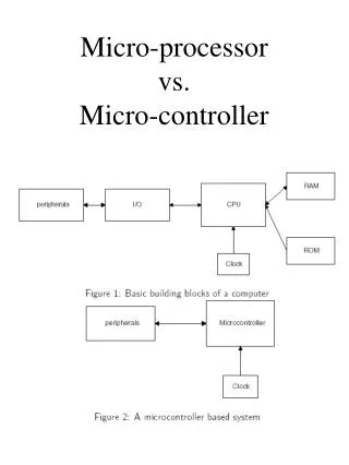
The Lab - Overview In Lab 01, you learned how to program the PIC Microcontroller running on the Development Board. You could write a bit of new code, and you could explain what various Assembly instructions do. You also had a general idea of how to read the hardware specification. In this lab you combine those skills, programming the PIC microcontroller to use its various hardware features. In this lab, you will have three very specific tasks. • Starting with code given to you, determine the frequency at which the 16F886 is running. • Modify or write code to handle an interrupt from the switch on the Development Board. • Modified or write code that allows you to store data in the EEPROM of the 16F886. CS140 - Lab04
Task 1: Determine the Frequency of the Board I have used the code from 03_Rotate.asm and modified it to change the frequency of the oscillator on the chip. You can read about this oscillator in Section 4 of the 16F886 spec. This new program can be found here. You must enter into this program the number of letters in your first and last name – this serves as a randomization so that you each have a unique frequency for your oscillator. There’s a bit of code that takes these numbers and uses them to set the oscillator. Feel free to read this code and understand what it does using the oscillator description in Section 4 of the 16F886 spec. ; These variables will randomize the code you're working with so everyone ; gets a unique problem. #define FirstName .5 ; Enter here the number of letters in your first name #define LastName .8 ; enter here the number of letters in your last name Time the rotating lights (you may need to change some delay code here) in order to figure out the oscillator frequency. You may find it helpful to run the original 03_Rotate.asm in order to make sure you understand how the calculation works. That program has an oscillator that has not been modifed by the “random” number being used in the program here. CS140 - Lab04
Task 2: Write your own Interrupt Handler In the previous lab, you’ve seen a number of programs that employ the switch, the interrupt handler, the timer for rotation, etc. Your goal in this Task is to use these components in a new way. Here’s what your program Task2.asm should do. Using the Debug Board, the switch must cause an interrupt. The switch toggles between two LED actions – an “all flash” mode in which all four LEDs are alternately on/off and a “rotate” mode similar to that in 03_Rotate.asm. The Pot does not need to be used unless you wish to. The frequency of flash/rotate can be constant. You can wire the switch to any pin on the PIC that you wish. . CS140 - Lab04
Task 2: Write your own Interrupt Handler • Helpful hints: • When I wrote this code, I tried to start with an existing program and rip it apart. This produced a very tangled program. I recommend you start from scratch using previous code as examples. • Your code will have various sections: • Start – sets up the registers to enable interrupts and make LEDs outputs • Delay – a subroutine as we’ve used before. • Interrupt Service Routine – hardware control goes here when switch changes state ( high low or low high. ) This routine can set the flash/rotate flag. • Main Loop – checks for flash/rotate modes and produces LED action. • You will need to program various registers to get the switch interrupt to work. Look at: • TRIS register to control if a pin is input or output. • IOCB register to specify interrupt on change • INTCON register to turn on interrupts • I found the Microchip document AN552 to be helpful – you can search on their website. CS140 - Lab04
Task 3: Write an EEPROM Reader/Writer • Write a program to store and load from EEPROM. Be able to store a number such that when you power the box down and then back up, that number appears in the lights. This means that the number has been stored in EEPROM and has been retained, even though the power was turned off. • Program Behavior: • When the program starts, read an EEPROM location (your choice which location you use) and display that number on the LEDs. • Every time the switch is pushed, increment the LEDs and also store that new number in the EEPROM. • This is essentially the behavior of 06_Debounce.asm; you may want to start with that code, or merely refer to it in order to get the correct structure. • When the program is working correctly, you should be able to unplug the Board at any time, and when you again plug it in, the same LEDs should be lit. • Read Section 10 of the 16F886 spec – all will be revealed to you. CS140 - Lab04
Task 3: Write an EEPROM Reader/Writer The code given in the 16F886 spec doesn’t really work. Here’s some modified code that seems OK. #define XX ; Your choice of locations ;;;;;;;;;;;;;;;;;;;;;;;;;;;;;;;;;;;;;;;;;;;;;;;;;;;;;;;;;;;;;;;;;;;;;;;;; ; This code is modified from that in the 16F886 Manual, Section 10.1.2 ; Enter: ; You must previoiusly have a #define that specifies the EEProm ; address where the data should be written. Here it's written ; as DATA_EE_ADDR ; Exit: ; W contains the value read from EEProm ;;;;;;;;;;;;;;;;;;;;;;;;;;;;;;;;;;;;;;;;;;;;;;;;;;;;;;;;;;;;;;;;;;;;;;;;; EEProm_Read: BANKSEL EEADR ; movlw DATA_EE_ADDR ; Address we're using in EEProm movwf EEADR ; Data Memory Address to read BANKSEL EECON1 ; bcf EECON1, EEPGD ; Specify using EEProm data memory bsf EECON1, RD ; Set RD bit to begin reading BANKSEL EEDAT movf EEDAT, W ; W = EEDAT BANKSEL STATUS ; Bank 0 return CS140 - Lab04
Task 3: Write an EEPROM Reader/Writer ;;;;;;;;;;;;;;;;;;;;;;;;;;;;;;;;;;;;;;;;;;;;;;;;;;;;;;;;;;;;;;;;;;;;;;;;; ; This code is modified from that in the 16F886 Manual, Section 10.1.2 ; Enter: ; On entry, W contains the value to be written ; You must previoiusly have a #define that specifies the EEProm ; address where the data should be written. ; Exit: ; No values are returned. Bank is restored to 0. ;;;;;;;;;;;;;;;;;;;;;;;;;;;;;;;;;;;;;;;;;;;;;;;;;;;;;;;;;;;;;;;;;;;;;;;;; EEProm_Write: BANKSEL EEADR ; movwf EEDATA ; Data Memory Value to write movlw DATA_EE_ADDR movwf EEADR ; Data Memory Address to write BANKSEL EECON1 bcf EECON1, EEPGD ; Specify using EEProm data memory bsf EECON1, WREN ; Enable writes movlw 55h ; Simply because the formula says to do this movwf EECON2 ; Write 55h to virtual address movlw 0xAA ; movwf EECON2 ; Write AAh bsf EECON1, WR ;Set WR bit to begin write EEProm_Loop: btfsc EECON1, WR ; When bit is clear, write has finished goto EEProm_Loop bcf EECON1, WREN ;Disable writes BANKSEL 0x00 ;Bank 0 -return to normal return CS140 - Lab04
Evaluation Sheet • Lab 04: Your Name:______________________ • DetermineFrequency.asm runs successfully on the Board. • Student can describe, in writing, the process by which s/he determined the frequency. • A correct number for the modified oscillator frequency is determined. • There is a design document showing the workings of the code for the Interrupt Handler. • Interrupt Handler works successfully • The interrupt handler program makes extensive use of subroutines, has limited use of goto’s, has good design, and is well commented. • EEPROM program works successfully. • EEPROM program has many subroutines and is well documented. CS140 - Lab04