Download
1 / 10
100 likes | 243 Vues
An FPGA Based Graph Coloring Accelerator. Lou Pochet Air Force Research Lab Information Directorate IFTC. Overview. Latin Squares/Wave Division Multiplexing Algorithm Overview Implementation Results Future Work. Latin Squares and Wave Division Multiplexing.

E N D
An FPGA Based Graph Coloring Accelerator Lou Pochet Air Force Research Lab Information Directorate IFTC
Overview • Latin Squares/Wave Division Multiplexing • Algorithm Overview • Implementation • Results • Future Work
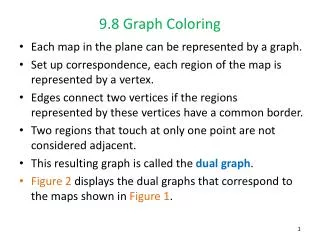
Latin Squares and Wave Division Multiplexing • Rule For Coloring Latin Squares: • Each color represented in a row/column exactly once • WDM Mapping Latin Squares • Color = Wavelength • Row = Input Port • Column = Output Port Output 1 2 3 4 1 2 3 4 Input
Motivation for Accelerator Project • Latin Squares with few preset colorations are easy to complete • As the number of presets increases, difficulty increases also Courtesy of Carla Gomes - Cornell
Algorithm Overview • Completing a Latin Square is an inherently Parallel process • Many simple comparisons required • Little need for Global information or communication • Array of small processors implemented
Algorithm from a Node Perspective • Only Memory “Bin” specific to a node state • Bin fills requested from edge when empty • Alternate reading/writing from/to row and column bus
Implementation • Design Directives: • Scaling key factor (Goal of completing an N=40 square) • Keep node processors simple • No global communication • Allow implication rules and implementation to be “tweaked”
Node Scaling Bin size variable Integer representation used to store colors Node Operations (5) Request fill (page out) Remove Color Implicate Signify Contradiction Guess Implementation
Results • 40 MHz design • 6000 slices for a 6x6 matrix –Bin depth = 4 • 4200 cycle overhead to complete an unconstrained graph • Latency causes bin consistency errors when more than one backtrack required – working on it • 40 cycles required to complete a backtrack and return to safe state
Future Work • Time Multiplexing (Windowing) • Partition Across Multiple FPGAs • Pipeline Node Processor Operation to increase clock speed