Download
1 / 17
170 likes | 276 Vues
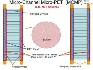
GTK Micro Channel Frame. Thermal layout. Georg Nüßle. Content. Model thermal frame (simulation) Layout channel geometry (analytical). Content. Model thermal frame (simulation) Layout channel geometry (analytical). Geometry and Boundaries. Cooling frame with sensor and chips.

E N D
GTK Micro Channel Frame Thermal layout Georg Nüßle
Content • Model thermal frame (simulation) • Layout channel geometry (analytical) GTK Cooling Meeting
Content • Model thermal frame (simulation) • Layout channel geometry (analytical) GTK Cooling Meeting
Geometry and Boundaries • Cooling frame with sensor and chips GTK Cooling Meeting
Geometry and Boundaries • Cooling frame with sensor and chips • Cut through complete assembly GTK Cooling Meeting
Geometry and Boundaries • Cooling frame with sensor and chips • Cut through complete assembly • ASIC digital part 6mm long • That means micro channel area 6mm wide 6mm GTK Cooling Meeting
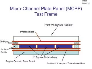
Geometry and Boundaries • Cooling frame with sensor and chips • Cut through complete assembly • ASIC digital part 6mm long • That means micro channel area 6mm wide • Simplified model: half model, slice of 1mm • Cover wafer 100µm thick • MC wafer 400µm thick • Channel height 300µm • Channel width 100µm • Wall width between channels 100µm GTK Cooling Meeting
Geometry and Boundaries Fixed temperature on channel walls, -20°C (Junction Temperature) Heat source: digital 4W/cm2, analog 0.5W/cm2 Glue between ASIC and mc frame, 0.3W/m/K Bonding between cover and mc wafer • Bump bonds, ASIC and Sensor, 0.12W/m/K • SnAG3.5 -> 33W/m/K • Pixel area 300µm x 300µm, bump diameter 20µm • Area ratio gives 0.12W/m/K for contiguous material Symmetry, front, back and right side GTK Cooling Meeting
Temperature Distribution ASIC 100µm thick ∆T over Sensor ~ 9.3°C -3.2837°C ~ -12.6°C ASIC 200µm thick ∆T over Sensor ~ 7.2°C -7.0151°C ~ -14.2°C GTK Cooling Meeting
Total Deformation Fixed support boundary condition Symmetry boundary condition Maximum Deformation ~ 3µm ASIC 200µm thick, fixed by symmetry boundary condition on the right side Maximum Deformation ~ 32µm ASIC 200µm thick, fixed by symmetry boundary condition on the right side and by gluing on the PCB (Fixed support) GTK Cooling Meeting
Thermal Stress Fixed support boundary condition Symmetry boundary condition Maximum Stress ~ 12.1MPa ASIC 200µm thick, fixed by symmetry boundary condition on the right side Maximum Stress ~ 65.7MPa ASIC 200µm thick, fixed by symmetry boundary condition on the right side and by gluing on the PCB (Fixed support) GTK Cooling Meeting
Content • Model thermal frame • Layout channel geometry (analytical) GTK Cooling Meeting
Constraints • Channel length 60mm • Width cooled area 6mm • ∆T between inlet and outlet 5K (-> m, ∆p) • Junction temperature = ∆TJ between wall and mean fluid temperature • ∆TJ depends on geometry and heat flux 60mm • K takes into account the ratio between the hydraulic area and the heat exchange area in a square shaped channel ∆TJ GTK Cooling Meeting
Influence of the Wall Width • Smaller walls lead to more channels and more heat exchange surface • ∆Tjunction and ∆pchannelrise with the wall width GTK Cooling Meeting
∆TJand ∆p with 50µm wall ∆pin_out ∆TJ ∆TJ/ ∆pin_out [K] / [bar] channel width [µm] GTK Cooling Meeting
∆TJand ∆p with 100µm wall ∆pin_out ∆TJ ∆TJ/ ∆pin_out [K] / [bar] channel width [µm] GTK Cooling Meeting
∆TJand ∆p with 200µm wall ∆pin_out ∆TJ ∆TJ/ ∆pin_out [K] / [bar] channel width [µm] GTK Cooling Meeting