Download
1 / 47
520 likes | 706 Vues
Finite elements for plates and shells. Plates and shells. A. Midplane. The mid-surface of a plate is plane, a curved geometry make it a shell The thickness is constant. May be isotropic, anisotropic, composite and layered. The isotropic case is considered.

E N D
Plates and shells A Midplane • The mid-surface of a plate is plane, a curved geometry make it a shell • The thickness is constant. • May be isotropic, anisotropic, composite and layered. • The isotropic case is considered. • Thin and thick cases are take into account. A
Comparison plate-beam • A plate can be regarded as the two-dimensional analogue of a beam: • - both carry transverse loads by bending action; • - but they have significant differences; • - a beam typically has a single bending moment; a plate has two bending moments (and two twisting moments) • - a deflection of a beam need not strain its axis; deflection of a plate will strain its midsurface Flessione di una trave Bending of a beam
Thin plates (Kirchhoff) t<1/10 the span of the plate w=w(x,y) Transverse shear deformation is neglected Arbitrary point P displacement
The strain displacement relations give the first of these equation is the only one used in the beam theory. In a thin plate the stress normal to the midplane is considered negligible Accordingly, the plane stress equation gives
Stress distribution • Like in a beam, stresses vary linearly with distance from the midsurface • Transverse shear stresses tyz and tzx are also present, even though transverse deformation is neglected • Transverse shear stresses vary quadratically through the thickness
Moments • The stresses give rise to bending moment Mx and My and twisting moment Mxy • Moments are function of x and y and are computed for unit length in the plane of the plate
Maximum magnitude of stresses • Formula for sx can be regarded as the flexure formula sx=Mxc/I applied to a unit width of the plate with c=t/2
Bending of a plate • A plate has a wide cross section - top and bottom edge of a cross section remain straight y-parallel axis when Mx is applied • When a plate is bent to a cylindrical surface, only Mx acts: • The flexural stress sx is accompanied by the stress sy • Stress sy constrains the plate against the deformation ey, thereby stiffening the plate • The amount of stiffening is proportional to 1/(1-n2), so that a unit width of the plate has
Thick plates (Mindlin) • Accounts for transverse shear deformation • The assumption that right angle in a cross section are preserved must be abandoned • The planes initially normal to the midsurface experience rotations different from rotations of the midsurface itself (x, y)
Strain-displacements relations If Transverse shear deformations vanish and the equations reduce to the equations for thin plates.
Loads • Loads in the z direction, either distribuited or concentrated,to the lateral surface z=t/2, or to the edge of the plate • Bending moment whose vector is tangent to the edge • At the point where concentrated lateral load (z direction) is applied: - Kirchhoff theory predicts infinite bending; - Mindlin theory predicts infinite bending and infinite displacement • The infinities disappear if the “concentrated” load is applied over a small area instead.
Membrane forces • Internal force resultant in the plane of the plate (membrane forces) • can develop as a consequence of the deflection • may be present because of loads component tangent to the midsurface • can significantly influence the response of the plate to load • Membrane forces have a stress stiffening effect: - if tensile they effectively increase the flexural rigidity - if compressive they decrease it • Compressive membrane forces may become large enough to produce buckling
Beam with immovable hinge supports • Hinge support remains exactly a distance L apart, regardless of how much load is applied. • Beam develop the usual flexural stresses and also membrane force N that support part of the applied load by spring effect. • If the deflected shape is a parabola with center deflection wc the uniform distributed load supported by spring action is
For a simple supported beam • The total load supported by beam and spring action occurring simultaneously is • For wc/t=0.5 (HP: t<<L) spring and beam action each support about half of the total load • This argument is of little value for beams because immovible supports are not found in practice. • The value of the argument is its implication for problems of thin plates
Observation • The counterpart of the spring action in a beam is strain of the midsurface in a plate. • Deflection of a plate w=w(x, y) produce no strain of the midsurface only if w describes a developable surface, i.e. cylinder or cone. • In general load produces a deflected shape that is not developable. • Accordingly, in general there are strains at the midsurface, and membrane forces appear that carry out part of the load.
Finite elements for plates • A plate is a thin solid and might be modeled by 3D solid elements • A solid element is wasteful of d.o.f., as it computes transverse normal stress and transverse shear stresses, all of which are considered negligible in a thin plate. • Also thin 3D elements invite numerical troubles because stiffness associated with ez is very much larger than other stiffnesses.
The plate element has half as many d.o.f. as the comparable 3D element and omit ez from its formulation • Thickness appear to be zero, but the correct value is used in its formulation • Circular plates can be modeled by shell of revolution elements, simply by making shell elements flat rather than cylindrical or conic. • Each of such element is thus a flat annular ring, joined to adjacent annular elements at its inner and outer radii.
Patch tests for plate elements • A plate element must be able to display states of constant sx, sy and txy if it is to pass patch test. • These states must be displayed in each z=constant layer. • This means that a valid plate element must pass patch tests for states of constant Mx, My, and Mxy.. Patch test for constant Mx
Kirchhoff plate elements 12 d.o.f. Nodal d.o.f.: • The assumed w field is a polynomial in x and y • The stiffness matrix is where D is the matrix of the flexural rigidities B is contrived to produce curvature when it operates on nodal d.o.f. that describe a lateral displacement field w=w(x,y)
This element is incompatible: that is , if n is a direction normal to an element edge, is not continuous between elements for some loading conditions • Accordingly, the element cannot guarantee a lower bound on computed displacements, so results may converge “from above” rather “from below”. • A compatible rectangular element with corner nodes only require that twist 2w/xy also be used as a nodal d.o.f. which is undesiderable. • Experience in formulation of plate elements has shown that the Midlin formulation is more productive and Midlin plate elements are in common use also for thin plates.
Mindlin plate elements • A Mindlin element is based on three fields • each interpolated from nodal values. • If all interpolations use the same polynomial, then for an element of n nodes:
In the stiffness matrix • D include the 3by 3 matrix for plane stress and also shear moduli associated with the two transverse shear strain. • Integration with respect ot z is done explicitly. • Integration in the plane of the element is done numerically if the element is isoparametric. • Four nodes and eight nodes quadrilater elements are popular based on the same Ni used for a plane elements. • In any layer z=constant, the behaviour of a Mindlin plate can be deduced from the behaviour of the corresponding element provided that the integrand are integrated by the same quadrature rule.
Bending deformation • Elements strains x are independentof x, any order o quadrature will report the same strain energy of pure bending • However this element displays spurious shear strain. • If a/t is large, transverse shear strain zx becomes large and the element is too stiff in bending, unless zx is evaluated at x=0, where it vanishes. • But one-point quadrature for all strains will introduce four instability modes.
This observation suggests “selective integration” in which one-point quadrature is applied to transverse shear terms and four-point quadrature is applied to bending terms. • Two instability modes remain that are controlled by “stabilization” matrices. • Eight nodes Mindlin elements have the analogous shortcomings and may also be treated by selective integration. • Calculated stresses are usually more accurate at the Gauss points.
Support conditions • Support conditions are classed as clamps, simple, or free, in direct analogy to the possible support conditions of a beam. • Nodal d.o.f. that must be prescribed for these support conditions are the following Clamped w=n= s=0 ------ Simply supported w=0 Mn=0 Free ------- Q=Mn=Mns=0
Bending of square plate Maximum deflection =0.00406 simply supported edges =0.00126 clamped edges Distributed load q Concentrated load P =0.0116 simply supported edges =0.00560 clamped edges
Twisting test cae E=107 =0.3 t=0.05 W3=0.0029 L
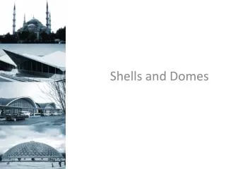
The geometry of a shell is defined by its thickness and its midsurface, which is a curved surface in space. • Load is carried by a combination of membrane action and bending action. • A thin shell can be very strong if membrane action dominates, in the same way that a wire can carry great load in tension but only small load in bending. • However, no shell is completely free of bending stresses. • They appear or near point load, line loads, reinforcements, junctures, change of curvature and supports. • Any concentration of load or geometrical discontinuity can be expected to produce bending stresses, often much larger, of membrane stresses, but quite localized. Shells and shell theory
Axial force G must be transferred through the structure to the support. • The simple support around the base AA applies axially direct line load, which has a shell normal component that causes bending. • Around BB the cylindrical and conical part exert shell-normal load component on one other. • Shell-normal load is transferred across FF because the cylindrical and spherical shells try to expand different amounts under internal pressure • Line load EE is obviously shell-normal, as is the restrain provided by reinforcing ring DD Example of load and geometry that produce bending
Internal forces and moments associated with bending at a discontinuity such as CC are the followingFlexural stress and bending moment in a shell are related in the same way as for a plateMembrane stresses, constant through the thickness, would be superposed on the flexural stress
How much is the boundary in which bending may be important? A simple approximation can be obtained from the theory of a shell of revolution. Analytical solution for radial displacement and bending moment as function of axial distance x from the end is Where, given R the radius and t the thickness of the shell, For x= 30.25 , e-x=0.07 (=0)x=Rt The end displacement and the bending moment declines to 7%. This is the estimate value of the boundary layer. In a FE analysis al least two element must be used to span the boundary layer.
Shell tangent edge loads Shell tangent edge loads produce actions that are not confined to a boundary layer . Axial loads act on end A of the unsupported cylindrical shell, but the largest displacement appear at the end B in apparent contradiction of Saint-Venant principle. Saint-Venant principle is applicable to massive isotropic boides. Thin-walled structure and high anisotropic structures may behave quite differently.
The most direct mode to obtain a shell element is to combine a membrane element and a bending element. • A simple triangular element can be obtained by combining the plane stress triangle with the plane bending triangle. • The resulting element is flat and has five d.o.f. or six d.o.f. per node, depending on whether or not the shell-normal rotation qzi at node i is present in the plane stress element. • A quadrilater element can be produced in similar fashion, by combining quadrilater plane and plate elements. • A four node quadrilater element is in general a warped element because its nodes are not all coplanar. • A modest amount of warping can seriously degrade the performance of an element. Finite elements for shells
Flat elements • Advantages of a flat element include: • - simplicity of formulation, • - simplicity in the description of the geometry, • - element’s ability to represent rigid-body motion without strain. • Disadvantage include: • - the representation of a smoothly curved shell surface by flat or slightly warped facets. • There is a discretization error associated with the lack of coupling between membrane and bending action within individual elements. • Common advice is that flat element should span no more than roughly 10° of the arc of the actual shell.
Curved elements based on shell theory avoid some shortcomings of flat elements but introduce other difficulties: • - more data are needed to describe the geometry of a curved element, • - formulation, based on shell theory, is complicated, • - membrane and bending action are coupled within the element
Isoparametric shell elements occupy a middle ground between flat elements and curved elements based on shell theory. • One begins with a 3d solid element • The element can model a shell if thickness t is small in comparison with other dimensions. • However, such an element has the defect noted for plate bending: invite numerical troubles because the stiffness associated with ez is very much larger than the other stiffness. Isoparametric shell elements
Accordingly , the element is transformed, the number of nodes is reduced from 20 to 8, by expressing translational d.o.f. of the 20-node element in terms of translational and rotational d.o.f. of the 8-node element. • Node A and C appear in the solid element, but not in the shell elements. Displacement at A and C are
With relations like these for all thickness direction lines of nodes, shape function of the 20 node element are transformed so as to operate on the three translations and two rotations at each node of the 8-node element. • A Mindlin shell element is obtained. • Thickness direction normal stress is taken as zero, and stress-strain relations reflect this assumption. • The element matrix is integrated numerically. • A reduced or selective integration scheme may be used to avoid transverse shear locking and membrane locking.
Test cases • Shell roof with q= 90 for unit area: membrane action dominates • Pinched cylinder, F=1: mambrane and bending action are active • Hemisphere, F=2: bending action dominates • Twisted strip: F1=10-6: sensitivity of the elements to warping can be tested
A Aaa Shell of revolution A Aaa A Aaa A Aaa A Aaa In cross section, an element for a shell of revolution resembles a beam element. Like an element for a solid of revolution, an element for a shell of revolution has nodal circle, rather than nodal points. Typically there are two nodal circles for element.
A shell of revolution element may be flat (conical) or curved. The simplest formulation resembles the 2D beam element , in that is used: - a cubic lateral displacement field, - a linear meridianal displacement field, - each nodal circle has two translational (radial and axial) and one rotational as d.o.f. Conical shell elements have advantages and disadvantages like those of other flat element Spherical shell loaded by internal pressure and modeled by a coarse mesh of conical shell elements display spurious bending moments.
From the beam behaviour • Shear center (x=-2R y=0) • Torque about the shear center T= -2RP • Rotation of the loaded end =-11.2 10-6 rad • Total deflection v=-37310-6+2R =-933 10-6 mm