Download
1 / 50
1.25k likes | 2.36k Vues
Chapter 16: Bulk Forming Processes. DeGarmo’s Materials and Processes in Manufacturing. 16.1 Introduction. Metal has been shaped by deformation processes for several thousand years Forging, rolling, and wire drawing were performed in the Middle Ages

E N D
Chapter 16:Bulk Forming Processes DeGarmo’s Materials and Processes in Manufacturing
16.1 Introduction • Metal has been shaped by deformation processes for several thousand years • Forging, rolling, and wire drawing were performed in the Middle Ages • The Industrial Revolution allowed these processes to be done at a higher level • Recently, many processes have begun to be automated
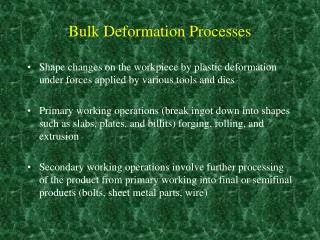
16.2 Classification of Deformation Processes • Bulk deforming processes can be classified as primary or secondary processes • Primary processes reduce a cast material into slabs, plates, and billets • Secondary processes reduce shapes into finished or semifinished products • Bulk deformation processes are those processes where the thickness or cross sections are reduced • Sheet-forming operations involve the deformation of materials whose thickness and cross section remain relatively constant
16.3 Bulk Deformation Processes • Rolling • Forging • Extrusion • Wire, rod, and tube drawing • Cold forming, cold forging, and impact extrusion • Piercing • Squeezing processes
16.4 Rolling • Rolling operations reduce the thickness or change the cross section of a material through compressive forces • Often the first process that is used to convert material into a finished wrought product • Thick stock can be rolled into blooms, billets, or slabs
Starting Stock • Blooms have a square or rectangular cross section • Billets are usually smaller than a bloom and can have a square or circular cross section • Can be further rolled into structural shapes • Slabs are a rectangular solid with a width greater than twice the thickness • Can be used to produce plates, sheets, or strips
Flowchart of Rolling Operations Figure 16-1 Flow chart for the production of various finished and semifinished steel shapes. Note the abundance of rolling operations. (Courtesy of American Iron and Steel Institute, Washington, D.C.)
Basic Rolling Process • Metal is passed between two rolls that rotate in opposite directions • Friction acts to propel the material forward • Metal is squeezed and elongates to compensate for the decrease in cross-sectional area Figure 16-2 Schematic representation of the hot-rolling process, showing the deformation and recrystallization of the metal being rolled.
Hot Rolling and Cold Rolling • In hot rolling, temperature control is required for successful forming • Temperature of the material should be uniform • Rolling is terminated when the temperature falls to about 50 to 100 degrees above the recrystallization temperature • Ensures the production of a uniform grain size • Cold rolling products sheet, strip, bar and rod products with smooth surfaces and accurate dimensions
Rolling Mill Configurations Figure 16-3 Various roll configurations used in rolling operations.
Rolling Mill Configurations Figure 16-4 The effect of roll diameter on length of contact for a given reduction. • Smaller diameter rolls produce less length of contact for a given reduction and require less force to produce a given change in shape • Smaller cross section provides a reduced stiffness • Rolls may be prone to flex elastically because they are only supported on the ends
Continuous (Tandem) Rolling Mills • Billets, blooms, and slabs are heated and fed through an integrated series of nonreversing rolling mills • Synchronization of rollers may pose issues Figure 16-5 Typical roll-pass sequences used in producing structural shapes.
Ring Rolling • One roll is placed through the hole of a thick-walled ring and a second roll presses on the outside • Produces seamless rings • Circumferential grain orientation and is used in rockets, turbines, airplanes, pressure vessels, and pipelines Figure 16-6 Schematic of horizontal ring rolling operation. As the thickness of the ring is reduced, its diameter will increase.
Characteristics, Quality, and Precision of Rolled Products • Hot-rolled products have little directionality in their properties • Hot-rolled products are therefore uniform and have dependable quality • Surfaces may be rough or may have a surface oxide known as mill scale • Dimensional tolerances vary with the kind of metal and the size of the product • Cold-rolled products exhibit superior surface finish and dimensional precision
Flatness Control and Rolling Defects • Rollers must be evenly spaced throughout for perfectly flat pieces to be produced • Sometimes this variation in roller “flatness” may be desired Figure 16-7 (above) (a) Loading on a rolling mill roll. The top roll is pressed upward in the center while being supported on the ends. (b) The elastic response to the three-point bending. Figure 16-8 Use of a “crowned” roll to compensate for roll flexure. When the roll flexes in three-point bending, the crowned roll flexes into flatness.
Thermomechanical Processing and Controlled Rolling • Heat may be used to reduce forces and promote plasticity, but heat treatments are typically subsequent operations • Thermomechanical processing combines the deformation and thermal processing into a single shape with the desired properties • Requires computer-controlled facilities • Substantial energy savings
16.5 Forging • Processes that induce plastic deformation through localized compressive forces applied through dies • Oldest known metalworking process • Parts can range in size • Methods • Drawing • Upset • Squeezed in closed impression dies
Open-die Hammer Forging • Same type of forging done by a blacksmith but mechanical equipment performs the operation • An impact is delivered by some type of mechanical hammer • Simplest industrial hammer is a gravity drop machine • Computer controlled-hammers can provide varying blows
Open-die Hammer Forging Figure 16-9 (Left) Double-frame drop hammer. (Courtesy of Erie Press Systems, Erie, PA.) (Right) Schematic diagram of a forging hammer.
Figure 16-10 (Top) Illustration of the unrestrained flow of material in open-die forging. Note the barrel shape that forms due to friction between the die and material. (Middle) Open-die forging of a multidiameter shaft. (Bottom) Forging of a seamless ring by the open-die method. (Courtesy of Forging Industry Association, Cleveland, OH.)
Impression-Die Hammer Forging • The dies are shaped to control the flow of metal • Upper piece attaches to the hammer and the lower piece to the anvil • Metal flows and completely fills the die Figure 16-11 Schematic of the impression-die forging process, showing partial die filling and the beginning of flash formation in the center sketch and the final shape with flash in the right-hand sketch.
Impression-Die Hammer Forging • Excess metal may squeeze out of the die • This metal is called flash • Flashless forging can be performed if the metal is deformed in a cavity that provides total confinement • Many forged products are produced with a series of cavities • First impression is called edging, fullering, or bending • Intermediate impressions are for blocking the metal to approximately its final shape • Final shape is given in its final forging operation
Figure 16-12 Impression drop-forging dies and the product resulting from each impression. The flash is trimmed from the finished connecting rod in a separate trimming die. The sectional view shows the grain flow resulting from the forging process. (Courtesy of Forging Industry Association, Cleveland, OH.)
Alternatives to Hammer and Anvil Arrangement • Two hammers may form a workpiece • Impactors operate with less noise and less vibration Figure 16-13 Schematic diagram of an impactor in the striking and returning modes. (Courtesy of Chambersburg Engineering Company, Chambersburg, PA)
Automatic Hot Forging • Slabs, billets, and blooms can be slid into one end of a room and hot-forged products can emerge at the other end, with every process automated Figure 16-19 (a) Typical four-step sequence to produce a spur-gear forging by automatic hot forging. The sheared billet is progressively shaped into an upset pancake, blocker forging, and finished gear blank. (b) Samples of ferrous parts produced by automatic hot forging at rates between 90 and 180 parts per minute. (Courtesy of National Machinery Company, Tiffin, OH.)
Roll Forging • Round or flat bar stock is reduced in thickness and increased in length • Produces products such as axles, tapered levers, and leaf springs • Little or no flash is produced Figure 16-20 (Top) Roll-forging machine in operation. (Right) Rolls from a roll-forging machine and the various stages in roll forging a part. (Courtesy of Ajax Manufacturing Company, Euclid, OH)
Figure 16-21 Schematic of the roll-forging process showing the two shaped rolls and the stock being formed. (Courtesy of Forging Industry Association, Cleveland, OH.)
Swaging • Also known as rotary swaging and radial forging • Uses external hammering to reduce the diameter or produce tapers or points on round bars of tubes
Swaging Figure 16-22 (Below) Tube being reduced in a rotary swaging machine. (Courtesy of the Timkin Company, Canton, OH.) Figure 16-24 (Below) A variety of swaged parts, some with internal details. (Courtesy of Cincinnati Milacron, Inc. Cincinnati, OH.) Figure 16-23 (Right) Basic components and motions of a rotary swaging machine. (Note: The cover plate has been removed to reveal the interior workings.) (Courtesy of the Timkin Company, Canton, OH.)
Net-Shape and Near-Net-Shape Forging • 80% of the cost of a forged-part can be due to post-forging operations • To minimize expense and waste, parts should be forged as close the final shape as possible • These processes are known as net-shape or precision forging
16.6 Extrusion • Metal is compressed and forced to flow through a shaped die to form a product with a constant cross section • May be performed hot or cold • A ram advances from one end of the die and causes the metal to flow plastically through the die • Commonly extruded metals: aluminum, magnesium, copper, and lead Figure 16-26 Direct extrusion schematic showing the various equipment components. (Courtesy of Danieli Wean United, Cranberry Township, PA.)
Typical Extruded Products Figure 16-27 Typical shapes produced by extrusion. (Left) Aluminum products. (Courtesy of Aluminum Company of America, Pittsburgh, PA.) (Right) Steel products. (Courtesy of Allegheny Ludlum Steel Corporation, Pittsburgh, PA.)
Advantages of Extrusion • Many shapes can be produced that are not possible with rolling • No draft is required • Amount of reduction in a single step is only limited by the equipment, not the material or the design • Dies are relatively inexpensive • Small quantities of a desired shape can be produced economically
Extrusion Methods • Direct extrusion • Solid ram drives the entire billet to and through a stationary die • Must provide power to overcome friction • Indirect extrusion • A hollow ram pushes the die back through a stationary, confined billet Figure 16-28 Direct and indirect extrusion. In direct extrusion, the ram and billet both move and friction between the billet and the chamber opposes forward motion. For indirect extrusion, the billet is stationary. There is no billet-chamber friction, since there is no relative motion.
Forces in Extrusion • Lubrication is important to reduce friction and act as a heat barrier • Metal flow in extrusion • Flow can be complex • Surface cracks, interior cracks and flow-related cracks need to be monitored • Process control is important Figure 16-29 Diagram of the ram force versus ram position for both direct and indirect extrusion of the same product. The area under the curve corresponds to the amount of work (force x distance) performed. The difference between the two curves is attributed to billet-chamber friction.
Extrusion of Hollow Shapes • Mandrels may be used to produce hollow shapes or shapes with multiple longitudinal cavities Figure 16-31 Two methods of extruding hollow shapes using internal mandrels. In part (a) the mandrel and ram have independent motions; in part (b) they move as a single unit.
Hydrostatic Extrusion • High-pressure fluid surrounds the workpiece and applies the force to execute extrusion • Billet-chamber friction is eliminated • High efficiency process • Temperatures are limited because the fluid acts as a heat sink • Seals must be designed to keep the fluid from leaking Figure 16-33 Comparison of conventional (left) and hydrostatic (right) extrusion. Note the addition of the pressurizing fluid and the O-ring and miter-ring seals on both the die and ram.
16.7 Wire, Rod, and Tube Drawing • Reduce the cross section of a material by pulling it through a die • Similar to extrusion, but the force is tensile Figure 16-37 Cold-drawing smaller tubing from larger tubing. The die sets the outer dimension while the stationary mandrel sizes the inner diameter. Figure 16-35 Schematic drawing of the rod-or bar-drawing process.
Tube and Wire Drawing • Tube sinking does not use a mandrel • Internal diameter precision is sacrificed for cost and a floating plug is used Figure 16-38 (Above) Tube drawing with a floating plug. Figure 16-39 Schematic of wire drawing with a rotating draw block. The rotating motor on the draw block provides a continuous pull on the incoming wire.
Figure 16-40 Cross section through a typical carbide wire-drawing die showing the characteristic regions of the contour. Figure 16-41 Schematic of a multistation synchronized wire-drawing machine. To prevent accumulation or breakage, it is necessary to ensure that the same volume of material passes through each station in a given time. The loops around the sheaves between the stations use wire tensions and feedback electronics to provide the necessary speed control.
16.8 Cold Forming, Cold Forging, and Impact Extrusion • Slugs of material are squeezed into or extruded from shaped die cavities to produce finished parts of precise shape and size • Cold heading is a form of upset forging • Used to make the enlarged sections on the ends of rod or wire (i.e. heads of nails, bolts, etc.) Figure 16-42 Typical steps in a shearing and cold-heading operation.
Impact Extrusion • A metal slug is positioned in a die cavity where it is struck by a single blow • Metal may flow forward, backward or some combination • The punch controls the inside shape while the die controls the exterior shape Figure 16-44 Backward and forward extrusion with open and closed dies.
Cold Extrusion Figure 16-45 (a) Reverse (b) forward (c) combined forms of cold extrusion. (Courtesy the Aluminum Association, Arlington, VA.) Figure 16-46 (Right) Steps in the forming of a bolt by cold extrusion, cold heading, and thread rolling. (Courtesy of National Machinery Co. Tiffin, OH.)
Figure 16-47 Cold-forming sequence involving cutoff, squaring, two extrusions, an upset, and a trimming operation. Also shown are the finished part and the trimmed scrap. (Courtesy of National Machinery Co., Tiffin, OH.) Figure 16-48 Typical parts made by upsetting and related operations. (Courtesy of National Machinery Co., Tiffin, OH.)
16.9 Piercing • Thick-walled seamless tubing can be made by rotary piercing • Heated billet is fed into the gap between two large, convex-tapered rolls • Forces the billet to deform into a rotating ellipse Figure 16-51 (Left) Principle of the Mannesmann process of producing seamless tubing. (Courtesy of American Brass Company, Cleveland, OH.) (Right) Mechanism of crack formation in the Mannesmann process.
16.10 Other Squeezing Processes • Roll extrusion- thin walled cylinders are produced from thicker-wall cylinders • Sizing-involves squeezing all or select regions of products to achieve a thickness or enhance dimensional precision • Riveting- permanently joins sheets or plates of material by forming an expanded head on the shank end of a fastener • Staking-permanently joins parts together when a segment of one part protrudes through a hole in the other
Other Squeezing Processes Figure 16-52 The roll-extrusion process: (a) with internal rollers expanding the inner diameter; (b) with external rollers reducing the outer diameter. Figure 16-55 Permanently attaching a shaft to a plate by staking. Figure 16-53 Joining components by riveting.
Other Squeezing Operations Figure 16-56 The coining process. • Coining- cold squeezing of metal while all of the surfaces are confined within a set of dies • Hubbing- plastically forms recessed cavities in a workpiece Figure 16-56 Hubbing a die block in a hydraulic press. Inset shows close-up of the hardened hub and the impression in the die block. The die block is contained in a reinforcing ring. The upper surface of the die block is then machined flat to remove the bulged metal.
16.11 Surface Improvement by Deformation Processing • Deformation processes can be used to improve or alter the surfaces of the metal • Peening- mechanical working of surfaces by repeated blows of impelled shot or a round-nose tool • Burnishing- rubbing a smooth, hard object under pressure over the minute surface irregularities • Roller burnishing- used to improve the size and finish of internal and external cylindrical and conical surfaces
Summary • There are a variety of bulk deformation processes • The main processes are rolling, forging, extrusion, and drawing • Each has limits and advantages as to its capabilities • The correct process depends on the desired shape, surface finish, quantity, etc.