Download
1 / 39
520 likes | 925 Vues
BULK DEFORMATION PROCESSES IN METALWORKING. ©2002 John Wiley & Sons, Inc. M. P. Groover, “Fundamentals of Modern Manufacturing 2/e”. Bulk Deformation.

E N D
BULK DEFORMATION PROCESSES IN METALWORKING ©2002 John Wiley & Sons, Inc. M. P. Groover, “Fundamentals of Modern Manufacturing 2/e”
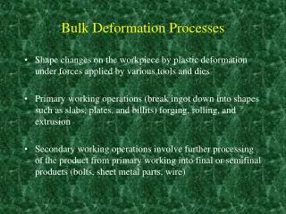
Bulk Deformation Metal forming operations which cause significant shape change by deformation in metal parts whose initial form is bulk rather than sheet • These processes work by stressing metal sufficiently to cause plastic flow into desired shape • Performed as cold, warm, and hot working operations
Importance of Bulk Deformation • In hot working, significant shape change can be accomplished • In cold working, strength can be increased during shape change • Little or no waste - some operations are near net shape or net shape processes • The parts require little or no subsequent machining
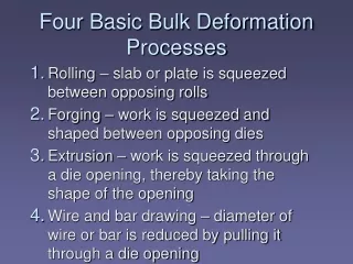
Four Basic Bulk Deformation Processes • Rolling – slab or plate is squeezed between opposing rolls • Forging – work is squeezed and shaped between opposing dies • Extrusion – work is squeezed through a die opening, thereby taking the shape of the opening • Wire and bar drawing – diameter of wire or bar is reduced by pulling it through a die opening
I. Rolling Deformation process in which work thickness is reduced by compressive forces exerted by two opposing rolls The rolling process (specifically, flat rolling)
The Rolls The rotating rolls perform two main functions: • Pull the work into the gap between them by friction between work-part and rolls • Simultaneously squeeze the work to reduce cross section
Types of Rolling • By geometry of work: • Flat rolling - used to reduce thickness of a rectangular cross-section • Shape rolling - a square cross-section is formed into a shape such as an I-beam • By temperature of work: • Hot Rolling – most common due to the large amount of deformation required • Cold rolling – produces finished sheet and plate stock
A rolling mill for hot flat rolling; the steel plate is seen as the glowing strip extending diagonally from the lower left corner (photo courtesy of Bethlehem Steel Company)
Various configurations of rolling mills (a) 2‑high rolling mill
Various configurations of rolling mills (b) 3‑high rolling mill
Various configurations of rolling mills (c) four‑high rolling mill
Various configurations of rolling mills (d) cluster mill
Various configurations of rolling mills (e) tandem rolling mill
Thread Rolling Bulk deformation process used to form threads on cylindrical parts by rolling them between two dies • Most important commercial process for mass producing bolts and screws • Performed by cold working in thread rolling machines • Advantages over thread cutting (machining): • Higher production rates • Better material utilization • Stronger threads due to work hardening • Better fatigue resistance due to compressive stresses introduced by rolling
Thread Rolling Thread rolling with flat dies: (1) start of cycle, and (2) end of cycle
Ring Rolling Deformation process in which a thick-walled ring of smaller diameter is rolled into a thin walled ring of larger diameter • As thick-walled ring is compressed, deformed metal elongates, causing diameter of ring to be enlarged • Hot working process for large rings and cold working process for smaller rings • Applications: ball and roller bearing races, steel tires for railroad wheels, and rings for pipes, pressure vessels, and rotating machinery • Advantages: material savings, ideal grain orientation, strengthening through cold working
Ring Rolling Ring rolling used to reduce the wall thickness and increase the diameter of a ring: (1) start, and (2) completion of process
II. Forging Deformation process in which work is compressed between two dies • Oldest of the metal forming operations, dating from about 5000 B C • Components: engine crankshafts, connecting rods, gears, aircraft structural components, jet engine turbine parts • In addition, basic metals industries use forging to establish basic form of large components that are subsequently machined to final shape and size
Classification of Forging Operations • Cold vs. hot forging: • Hot or warmforging– most common, due to the significant deformation and the need to reduce strength and increase ductility of work metal • Cold forging- advantage is increased strength that results from strain hardening • Impact vs. press forging: • Forge hammer- applies an impact load • Forge press- applies gradual pressure
Types of Forging Dies • Open‑die forging- work is compressed between two flat dies, allowing metal to flow laterally without constraint • Impression‑die forging- die surfaces contain a cavity or impression that is imparted to workpart, thus constraining metal flow - flash is created • Fleshless forging- workpart is completely constrained in die and no excess flash is produced
1. Open‑DieForging Compression of workpart with cylindrical cross‑section between two flat dies • Similar to compression test • Deformation operation reduces height and increases diameter of work • Common names include upsetting or upset forging
2. Impression‑DieForging Compression of workpart by dies with inverse of desired part shape • Flash is formed by metal that flows beyond die cavity into small gap between die plates • Flash must be later trimmed from part, but it serves an important function during compression: • As flash forms, friction resists continued metal flow into gap, constraining material to fill die cavity • In hot forging, metal flow is further restricted by cooling against die plates Sequence in impression‑die forging: • just prior to initial contact with raw workpiece, • partial compression, and • final die closure, causing flash to form in gap between die plates
Impression‑Die Forging Advantages and Limitations • Advantages compared to machining from solid stock: • Higher production rates • Conservation of metal (less waste) • Greater strength • Favorable grain orientation in the metal • Limitations: • Not capable of close tolerances • Machining often required to achieve accuracies and features needed, such as holes, threads, and mating surfaces that fit with other components
3. FlashlessForging Compression of work in punch and die tooling whose cavity does allow for flash • Starting workpart volume must equal die cavity volume within very close tolerance • Process control more demanding than impression‑die forging • Best suited to part geometries that are simple and symmetrical • Often classified as a precision forging process Flashless forging: • just before initial contact with workpiece, • partial compression, and • final punch and die closure
Forging Hammers (Drop Hammers) • Apply an impact load against workpart - two types: • Gravity drop hammers - impact energy from falling weight of a heavy ram • Power drop hammers - accelerate the ram by pressurized air or steam • Disadvantage: impact energy transmitted through anvil into floor of building • Most commonly used for impression-die forging Diagram showing details of a drop hammer for impression‑die forging
Forging Presses • Apply gradual pressure to accomplish compression operation - types: • Mechanical presses - converts rotation of drive motor into linear motion of ram • Hydraulic presses - hydraulic piston actuates ram • Screw presses - screw mechanism drives ram
III. Extrusion Compression forming process in which the work metal is forced to flow through a die opening to produce a desired cross‑sectional shape • Process is similar to squeezing toothpaste out of a toothpaste tube • In general, extrusion is used to produce long parts of uniform cross-sections • Two basic types of extrusion: • Direct extrusion • Indirect extrusion Direct extrusion
Comments on Direct Extrusion • Also called forward extrusion • As ram approaches die opening, a small portion of billet remains that cannot be forced through die opening • This extra portion, called the butt, must be separated from extruded product by cutting it just beyond the die exit • Starting billet cross section usually round, but final shape is determined by die opening (a) Direct extrusion to produce a hollow or semi‑hollowcross‑section; (b) hollow and (c) semi‑hollow cross‑ sections
Comments on Indirect Extrusion • Also called backward extrusion and reverse extrusion • Limitations of indirect extrusion are imposed by the lower rigidity of hollow ram and difficulty in supporting extruded product as it exits die Indirect extrusion to produce (a) a solid cross‑section and (b) a hollow cross‑section
General Advantages of Extrusion • Variety of shapes possible, especially in hot extrusion • Limitation: part cross‑section must be uniform throughout length • Grain structure and strength enhanced in cold and warm extrusion • Close tolerances possible, especially in cold extrusion • In some operations, little or no waste of material
Hot vs. Cold Extrusion • Hot extrusion - prior heating of billet to above its recrystallization temperature • This reduces strength and increases ductility of the metal, permitting more size reductions and more complex shapes • Cold extrusion - generally used to produce discrete parts • The term impact extrusion is used to indicate high speed cold extrusion
A complex extruded cross‑section for a heat sink (photo courtesy of Aluminum Company of America)
IV. Wire and Bar Drawing Cross‑section of a bar, rod, or wire is reduced by pulling it through a die opening • Similar to extrusion except work is pulled through die in drawing (it is pushed through in extrusion) • Although drawing applies tensile stress, compression also plays a significant role since metal is squeezed as it passes through die opening Figure 19.41 ‑ Drawing of bar, rod, or wire
Wire Drawing vs. Bar Drawing • Difference between bar drawing and wire drawing is stock size • Bar drawing - large diameter bar and rod stock • Wiredrawing - small diameter stock - wire sizes down to 0.03 mm (0.001 in.) are possible • Although the mechanics are the same, the methods, equipment, and even terminology are different
Drawing Practice and Products • Drawing practice: • Usually performed as cold working • Most frequently used for round cross‑sections • Products: • Wire: electrical wire; wire stock for fences, coat hangers, and shopping carts • Rod stock for nails, screws, rivets, and springs • Bar stock: metal bars for machining, forging, and other processes
Wire Drawing • Continuous drawing machines consisting of multiple draw dies (typically 4 to 12) separated by accumulating drums • Each drum (capstan) provides proper force to draw wire stock through upstream die • Each die provides a small reduction, so desired total reduction is achieved by the series • Annealing sometimes required between dies Continuous drawing of wire
Bar Drawing • Accomplished as a single‑draft operation ‑ the stock is pulled through one die opening • Beginning stock has large diameter and is a straight cylinder • This necessitates a batch type operation Hydraulically operated draw bench for drawing metal bars
BULK DEFORMATION PROCESSES IN METALWORKING • Rolling • Forging • Extrusion • Wire and Bar Drawing