Download
1 / 35
400 likes | 782 Vues
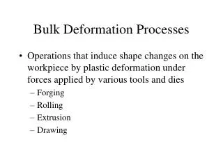
Chapter 16 Bulk Forming Processes (Part 1: Rolling & Forging) (Review) EIN 3390 Manufacturing Processes Fall, 2011. Bulk deforming processes can be classified as 1) Primary or secondary processes Primary processes reduce a cast material into slabs, plates, and billets

E N D
Chapter 16Bulk Forming Processes(Part 1: Rolling & Forging)(Review)EIN 3390 Manufacturing ProcessesFall, 2011
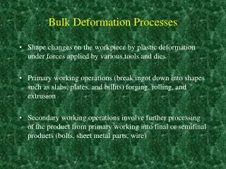
Bulk deforming processes can be classified as 1) Primaryor secondary processes • Primary processes reduce a cast material into slabs, plates, and billets • Secondary processes reduce shapes into finished or semifinished products 16.2 Classification of Deformation Processes
2) Bulk deformation processes and sheet-forming operation • Bulk deformation processes are those processes where the thickness or cross sections are reduced • Rolling, forging, extrusion, cold forming, wire, rod, and tube drawing • Sheet-forming operations involve the deformation of materials whose thickness and cross section remain relatively constant • Shearing, blanking, bending, and deep drawing • 3) Hot-working processes and cold-working processes 16.2 Classification of Deformation Processes (continue)
Rolling • Forging • Extrusion • Wire, rod, and tube drawing • Cold forming, cold forging, and impact extrusion • Piercing • Squeezing processes 16.3 Bulk Deformation Processes
Rolling operations reduce the thickness or change the cross section of a material through compressive forces • Often the first process that is used to convert material into a finished wrought product • Thick stock can be rolled into blooms, billets, or slabs 16.4 Rolling
Blooms have a square or rectangularcross section • Billets are usually smaller than a bloom and can have a square or circular cross section • Can be further rolled into structural shapes • Slabs are a rectangular solid with a width greater than twice the thickness • Can be used to produce plates, sheets, or strips Starting Stock
Figure 16-1 Flow chart for the production of various finished and semifinished steel shapes. Note the abundance of rolling operations. (Courtesy of American Iron and Steel Institute, Washington, D.C.) Flowchart of Rolling Operations
Basic Rolling Process • Metal is passed between two rolls that rotate in opposite directions • Friction acts to propel the material forward • Metal is squeezed and elongates to compensate for the decrease in cross-sectional area Figure 16-2 Schematic representation of the hot-rolling process, showing the deformation and recrystallization of the metal being rolled.
In hot rolling, temperature control is required for successful forming • Temperature of the material should be uniform • Rolling is terminated when the temperature falls to about 50 to 1000C degrees above the recrystallization temperature • Ensures the production of a uniform grain size and prevent unwanted strain hardening. • Cold rolling products sheet, strip, bar and rod products with smooth surfaces and accurate dimensions Hot Rolling and Cold Rolling
For products with uniform cross section and cross-sectional dimensions less than 5 cm (2 inch) cold rolling of rod or bar may be an attractive alternative to extrusion or machining. • Strain hardening can provide up to 20% additional strength to the metal. Cold Rolling
Rolling Mill Configurations Figure 16-4 The effect of roll diameter on length of contact for a given reduction. • Smaller diameter rolls produce less length of contact for a given reduction and require less force to produce a given change in shape • Smaller cross section provides a reduced stiffness • Rolls may be prone to flex elastically because they are only supported on the ends
F = F =
Figure 16-3 Various roll configurations used in rolling operations. Rolling Mill Configurations
A two- or three-high configuration with rolls 60 to 140cm (24 to 55 in) in diameter. Four-high and cluster arrangements use backup rolls to support the smaller work rolls. Foil is always rolled on cluster mills since the small thickness requires small-diameter roll. In a cluster mill, the roll in contact with work piece can be as small as 6 mm (0.23 in). Rolling Mill Configurations
t0W0v0 = tfw0vf vf = (t0 v0)/tf vf > vr > v0
At the entrance to the roll, the surface of the rolls is traveling at a speed vrthat is greater than the velocity v0of the incoming strip. At the exit area, the velocity vfof the strip is greater than the roll surface velocity vr . There is a region near the exit where friction actually opposes forward motion, and there is a point called “neutral point” where vrandvf are the same. The ideal rolling condition would be to have the neutral point near the exit but sufficiently within.
RingRolling • One roll is placed through the hole of a thick-walled ring and a second roll presses on the outside • Produces seamless rings • Circumferential grain orientation and is used in rockets, turbines, airplanes, pressure vessels, and pipelines Figure 16-6 Schematic of horizontal ring rolling operation. As the thickness of the ring is reduced, its diameter will increase.
Hot-rolled products have little directionality in their properties • Hot-rolled products are therefore uniform and have dependable quality • Surfaces may be rough or may have a surfaceoxide known as mill scale • Dimensional tolerances vary with the kind of metal and the size of the product • Cold-rolled products exhibit superior surface finish and dimensional precision Characteristics, Quality, and Precision of Rolled Products
Flatness Control and Rolling Defects • Rollers must be evenly spaced throughout for perfectly flat pieces to be produced • Sometimes this variation in roller “flatness” may be desired Figure 16-7 (above) (a) Loading on a rolling mill roll. The top roll is pressed upward in the center while being supported on the ends. (b) The elastic response to the three-point bending. Figure 16-8 Use of a “crowned” roll to compensate for roll flexure. When the roll flexes in three-point bending, the crowned roll flexes into flatness.
Processes that induce plastic deformation through localized compressive forces applied through dies • Oldest known metalworking process • Parts can range in size from ones whose largest dimension is less than 2 cm to others weighingmore than 170 metric tons (450,000 lb) 16.5 Forging
Drawn out • To increase part length and decrease its cross section • Upset • To decrease part length and increase its cross section • Squeezed in closed impression dies • To produce multidirectional flow Forging Methods
Open-die drop-hammer forging • Impression-die drop-hammer forging • Press forging • Upset forging • Automatic hot forging • Roll forging • Swaging • Net-shape and near-net-shape forging Common Forging Processes
Same type of forging done by a blacksmith but mechanical equipment performs the operation • An impact is delivered by some type of mechanical hammer • Simplest industrial hammer is a gravity drop machine • Computer controlled-hammers can provide varying blows Open-die Hammer Forging
Figure 16-10 (Top) Illustration of the unrestrained flow of material in open-die forging. Note the barrel shape that forms due to friction between the die and material. (Middle) Open-die forging of a multidiameter shaft. (Bottom) Forging of a seamless ring by the open-die method. (Courtesy of Forging Industry Association, Cleveland, OH.)
Impression-Die Hammer Forging • The dies are shaped to control the flow of metal • Upper piece attaches to the hammer and the lower piece to the anvil • Metal flows and completely fills the die Figure 16-11 Schematic of the impression-die forging process, showing partial die filling and the beginning of flash formation in the center sketch and the final shape with flash in the right-hand sketch.
Excess metal may squeeze out of the die • This metal is called flash • Flashless forging can be performed if the metal is deformed in a cavity that provides total confinement • Many forged products are produced with a series of cavities • First impression is called edging, fullering, or bending • Intermediate impressions are for blocking the metal to approximately its final shape • Final shape is given in its final forging operation Impression-Die Hammer Forging
Press forging is used for large or thick products • Slow squeezing action penetrates completely through the metal • Produces a more uniform deformation and flow • Longer time of contact between the die and workpiece • Dies may be heated (isothermal forging) • Presses are either mechanical or hydraulic Press Forging
Forging dies are typically made of high-alloy or tool steel • Rules for better and more economical parts: • Dies should part along a single, flat plane or follow the contour of the part • Parting surface should be a plane through the center of the forging • Adequate draft • Generous fillets and radii • Ribs should be low and wide • Various cross sections should be balanced • Full advantage should be taken of fiber flow lines • Dimensional tolerances should not be closer than necessary Design of Impression-Die Forgings and Associated Tooling
Impression-Die Forgings • Important design details • Number of intermediate steps • Shape of each step • Amount of excess metal to fill the die • Dimensions of flash at each step • Good dimensional accuracy Figure 16-15 A forged-and-machined automobile engine crankshaft that has been formed from microalloyed steel. Performance is superior to cranks of cast ductile iron.
Increases the diameter of a material by compressing its length • Both cold and hot upsetting • Three rules of upset forging • 1. The length of the unsupported material that can be gathered or upset in one blow without injurious buckling should be limited to three times the diameter of the bar. • 2. Lengths of stock greater than three times the diameter may be upset successfully provided that the diameter of the upset is not more than 1 times the diameter of the bar. Upset Forging
3. In an upset requiring stock length greater than three times the diameter of the bar, and where the diameter of the cavity is more than 1 times the diameter of the bar (the conditions of rule 2), the length of the unsupported metal beyond the face of the die must not exceed the diameter of the bar. Upset Forging
Upset Forging Figure 16-17 Schematics illustrating the rules governing upset forging. (Courtesy of National Machinery Company, Tiffin, OH.)
Swaging • Also known as rotary swaging and radial forging • Uses external hammering to reduce the diameter or produce tapers or points on round bars of tubes
Swaging Figure 16-21 (Below) Tube being reduced in a rotary swaging machine. (Courtesy of the Timkin Company, Canton, OH.) Figure 16-23 (Below) A variety of swaged parts, some with internal details. (Courtesy of Cincinnati Milacron, Inc. Cincinnati, OH.) Figure 16-22 (Right) Basic components and motions of a rotary swaging machine. (Note: The cover plate has been removed to reveal the interior workings.) (Courtesy of the Timkin Company, Canton, OH.)