Download
1 / 21
210 likes | 302 Vues
Digital Camera. Chad Hantak COMP290-052 December 12, 2003. Hardware Overview. XSA-100 connected to XST-2 XStend C3188A Camera Module Lens Omnivision 7620 CMOS USB Mod2. XStend Board. Brings out pins of XSA to a prototyping area Extended Hardware More SRAM IDE Etc.

E N D
Digital Camera Chad Hantak COMP290-052 December 12, 2003
Hardware Overview • XSA-100 connected to XST-2 XStend • C3188A Camera Module • Lens • Omnivision 7620 CMOS • USB Mod2
XStend Board • Brings out pins of XSA to a prototyping area • Extended Hardware • More SRAM • IDE • Etc.
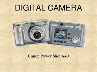
C3188A Camera Module • Mounted Lens • Minimum pins from CMOS Sensor • Clock
OmniVision OV7620 • CMOS / Digital • VGA, QVGA • YCrCb, GRB, RGB • 16 / 8 bit color • Interlaced / Progressive • Configurable via I2C • Many, many imaging options
USB Mod2 • FIFO via USB
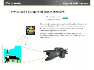
Crash Course on CMOS • Important signals • VSYNC, HREF, PCLK • VSYNC • Indicates start of frame • HREF • High during active pixel window • PCLK • Every rising edge pixels present on data lines
Crash Course on I2C • Simple 2-line multi-master bus • Lines • Serial Clock • Serial Data • Devices have two addresses (Reading / Writing) • Typically slow, just used for configuration • Protocol / Information can be found at: • http://www.semiconductors.philips.com/buses/i2c/facts/
Implemented Hardware • Show and Tell Time • Wire wrapping • Soldering
Flow Control • Initialization / Wait for go • Wait for a VSYNC • Grab pixels till end of VSYNC • Count # of pixels • Dump captured pixels to USB • Check for a command • Repeat
Command Processor • Two Internal Systems • Controller • Read Register • Write Register • Start • I2C Interface to the Sensor • Looks like a simple memory interface • Hides I2C from outside components
Image Sensor Interface • Operates on the pixel clock from the sensor • Tracks whether or not on a valid line (In Raw RGB mode, first HREF line is invalid) • Munges the data bits from Y, UV Channels and places it on the data bus
Memory Controller • What data bits go where • Two FIFOs • Controls SDRAM • Counting of data to and from SDRAM
What Went Wrong? (Fixed) • Two different clocks • System 50Mhz, Pixel Clock 27Mhz • Missing Pixels • Dual-Clocked FIFO • Fills on the pixel clock, drained on the system clock
What Went Wrong? (Broken) • I2C Does not work • Simulates Great • No good on hardware • Claims Opencores component may be flakey? • Intermittent USB->PC transfer problem • One build, works great • Next build, state machine in transfer system hangs • Bridged signal?
Where from here? • Debugging I2C • Can’t use ChipScope • Serial clock line running on 100 KHz clock • Use a standard analyzer • Check the hardware over • Rewire wrap all the signals • Look for bridged connections