Download
1 / 34
340 likes | 424 Vues
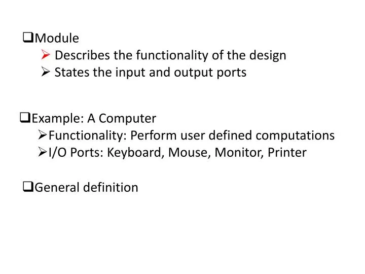
Module Describes the functionality of the design States the input and output ports. Example: A Computer Functionality: Perform user defined computations I/O Ports: Keyboard, Mouse, Monitor, Printer. General definition. General definition module module_name ( port_list );

E N D
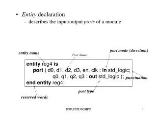
Module • Describes the functionality of the design • States the input and output ports • Example: A Computer • Functionality: Perform user defined computations • I/O Ports: Keyboard, Mouse, Monitor, Printer • General definition
General definition modulemodule_name ( port_list ); port declarations; … variable declaration; … description of behavior endmodule
Example module HalfAdder (A, B, Sum, Carry); inputA, B; outputSum, Carry; assignSum = A ^ B; //^ denotes XOR assignCarry = A & B; // & denotes AND endmodule
Lexical Conventions • Comments // Single line comment /* Another single line comment */ /* Begins multi-line (block) comment All text within is ignored Line below ends multi-line comment */ • Number decimal, hex, octal, binary unsized decimal form size base form include underlines, +,- • String " Enclose between quotes on a single line"
Lexical Conventions (cont.) • Identifier A ... Z a ... z 0 ... 9 Underscore • Strings are limited to 1024 chars • First char of identifier must not be a digit • Keywords: See text. • Operators: See text. Verilog is case sensitive
Description Styles b sel_b sel a1 n1 sel_n out o1 a a2 sel_a • Structural: Logic is described in terms of Verilog gate primitives • Example: notn1(sel_n, sel); anda1(sel_b, b, sel_b); anda2(sel_a, a, sel); oro1(out, sel_b, sel_a);
a Black Box 2x1 MUX out b sel Description Styles (cont.) • Behavioral: Algorithmically specify the behavior of the design • Example: if (select == 0) begin out = b; end else if (select == 1) begin out = a; end
Dataflow Modeling • Uses continuous assignment statement • Format: assign[ delay ] net = expression; • Example: assignsum = a ^ b; • Delay: Time duration between assignment from RHS to LHS • All continuous assignment statements execute concurrently • Order of the statement does not impact the design
Dataflow Modeling (cont.) • Delay can be introduced • Example: assign#2 sum = a ^ b; • “#2” indicates 2 time-units • No delay specified : 0 (default) • Associate time-unit with physical time • `timescale time-unit/time-precision • Example: `timescale 1ns/100 ps • Timescale `timescale1ns/100ps • 1 Time unit = 1 ns • Time precision is 100ps (0.1 ns) • 10.512ns is interpreted as 10.5ns
Dataflow Modeling (cont.) • Example: `timescale 1ns/100ps module HalfAdder (A, B, Sum, Carry); input A, B; output Sum, Carry; assign #3 Sum = A ^ B; assign #6 Carry = A & B; endmodule
Behavioral Modeling • Example: module mux_2x1(a, b, sel, out); inputa, a, sel; outputout; always@(a or b or sel) begin if (sel == 1) out = a; else out = b; end endmodule Sensitivity List
Behavioral Modeling (cont.) • always statement : Sequential Block • Sequential Block: All statements within the block are executed sequentially • When is it executed? • Occurrence of an event in the sensitivity list • Event: Change in the logical value • Statements with a Sequential Block: Procedural Assignments • Delay in Procedural Assignments • Inter-Statement Delay • Intra-Statement Delay
Behavioral Modeling (cont.) • Inter-Assignment Delay • Example: Sum = A ^ B; #2 Carry = A & B; • Delayed execution • Intra-Assignment Delay • Example: Sum = A ^ B; Carry = #2 A & B; • Delayed assignment
Procedural Constructs • Two Procedural Constructs • initial Statement • always Statement • initial Statement : Executes only once • always Statement : Executes in a loop • Example: … initial begin Sum = 0; Carry = 0; end … … always @(A or B) begin Sum = A ^ B; Carry = A & B; end …
Event Control • Event Control • Edge Triggered Event Control • Level Triggered Event Control • Edge Triggered Event Control @ (posedgeCLK) //Positive Edge of CLK Curr_State = Next_state; • Level Triggered Event Control @ (A or B) //change in values of A or B Out = A & B;
Loop Statements • Loop Statements • Repeat • While • For • Repeat Loop • Example: repeat (Count) sum = sum + 5; • If condition is a x or z it is treated as 0
Loop Statements (cont.) • While Loop • Example: while (Count < 10) begin sum = sum + 5; Count = Count +1; end • If condition is a x or z it is treated as 0 • For Loop • Example: for (Count = 0; Count < 10; Count = Count + 1) begin sum = sum + 5; end
Conditional Statements • if Statement • Format: if (condition) procedural_statement else if (condition) procedural_statement else procedural_statement • Example: if (Clk) Q = 0; else Q = D;
Conditional Statements (cont.) • Case Statement • Example 1: case (X) 2’b00: Y = A + B; 2’b01: Y = A – B; 2’b10: Y = A / B; endcase • Example 2: case (3’b101 << 2) 3’b100: A = B + C; 4’b0100: A = B – C; 5’b10100: A = B / C; //This statement is executed endcase
Data Types • Net Types: Physical Connection between structural elements • Register Type: Represents an abstract storage element. • Default Values • Net Types : z • Register Type : x • Net Types: wire, tri, wor, trior, wand, triand, supply0, supply1 • Register Types : reg, integer, time, real, realtime
Data Types • Net Type: Wire wire [ msb : lsb ] wire1, wire2, … • Example wire Reset; // A 1-bit wire wire [6:0] Clear; // A 7-bit wire • Register Type: Reg reg [ msb : lsb ] reg1, reg2, … • Example reg [ 3: 0 ] cla; // A 4-bit register reg cla; // A 1-bit register
Compiler Directives • `define – (Similar to #define in C) used to define global parameter • Example: `define BUS_WIDTH 16 reg [ `BUS_WIDTH - 1 : 0 ] System_Bus; • `undef – Removes the previously defined directive • Example: `define BUS_WIDTH 16 … reg [ `BUS_WIDTH - 1 : 0 ] System_Bus; … `undef BUS_WIDTH
Test-bench • To simulate design, you need both the design under test (DUT) or unit under test (UUT) and the stimulus provided by the test bench. • A test bench is HDL code that allows you to provide a documented, repeatable set of stimuli that is portable across different simulators. A test bench can be as simple as a file with clock and input data or a more complicated file that includes error checking, file input and output, and conditional testing.
In other words Testbenchis a program or model written in any language for the purposes of exercising and verifying the functional correctness of a hardware model during the simulation. Verilog is primarily a means for hardware modeling (simulation), the language contains various resources for formatting, reading, storing, allocating dynamically, comparing, and writing simulation data, including input stimulus and output results.
The major components of a testbench are: • `timescale declaration • -Specify the time unit for all delays • Module, which defines the testbench top-level structure • -A testbench usually does not have ports • Internal signals, which will drive the stimuli into the UUT and monitor the response from the UUT • -Signal to drive and monitor • UUT instantiation • Stimuli generation • -Write statements to create stimulus and procedural block • Response monitoring and comparing • -Self-testing statements that will report values, error, and warnings • -$display, $write, $strobe, and/or $monitor system tasks
Verilog Code of NOT gate // notgate.v // NOT gate // `timescale 1ns / 1ps module NOTgate1(A, F); input A; output F; reg F; always @ (A) begin F <= ~A; end endmodule
// notgate_tb.v // NOT gate testbench `timescale 1ns / 1ps module Testbench; regA_t; wire F_t; NOTgate1 NOTgate1_1(A_t, F_t); initial begin //case 0 A_t <= 0; #1 $display("F_t = %b", F_t); //case 1 A_t <= 1; #1 $display("F_t = %b", F_t); end endmodule Test-bench-NOT gate
// and2_tb.v `timescale 1ns / 1ps module Testbench; regA_t, B_t; wire F_t; AND2gate AND2gate_1(A_t, B_t, F_t); Initial begin //case 0 A_t <= 0; B_t <= 0; #1 $display("F_t = %b", F_t); //case 1 A_t <= 0; B_t <= 1; #1 $display("F_t = %b", F_t); //case 2 A_t <= 1; B_t <= 0; #1 $display("F_t = %b", F_t); //case 3 A_t <= 1; B_t <= 1; #1 $display("F_t = %b", F_t); end endmodule Test-bench
Design Module Test Bench `timescale 1ns/100ps module Top; reg PA, PB; wire PSum, PCarry; HalfAdder G1(PA, PB, PSum, PCarry); initialbegin: LABEL reg [2:0] i; for (i=0; i<4; i=i+1) begin {PA, PB} = i; #5 $display (“PA=%b PB=%b PSum=%b PCarry=%b”, PA, PB, PSum, PCarry); end // for end // initial endmodule Test Bench Apply Inputs Observe Outputs
Verilog code of 2-input AND gate // and2gate.v // 2-input AND gate // `timescale 1ns / 1ps module AND2gate(A, B, F); input A; input B; output F; reg F; always @ (A or B) begin F <= A & B; end endmodule
Test Bench - Generating Stimulus • Example: A sequence of values initialbegin Clock = 0; #50 Clock = 1; #30 Clock = 0; #20 Clock = 1; end
Test Bench - Generating Clock • Repetitive Signals (clock) Clock • A Simple Solution: wire Clock; assign #10 Clock = ~ Clock • Caution: • Initial value of Clock (wire data type) = z • ~z = x and ~x = x
Test Bench - Generating Clock (contd) • Initialize the Clock signal initialbegin Clock = 0; end • Caution: Clock is of data type wire, cannot be used in an initial statement • Solution: reg Clock; … initial begin Clock = 0; end … always begin #10 Clock = ~ Clock; end forever loop can also be used to generate clock