Download
1 / 28
510 likes | 2.47k Vues
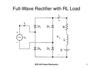
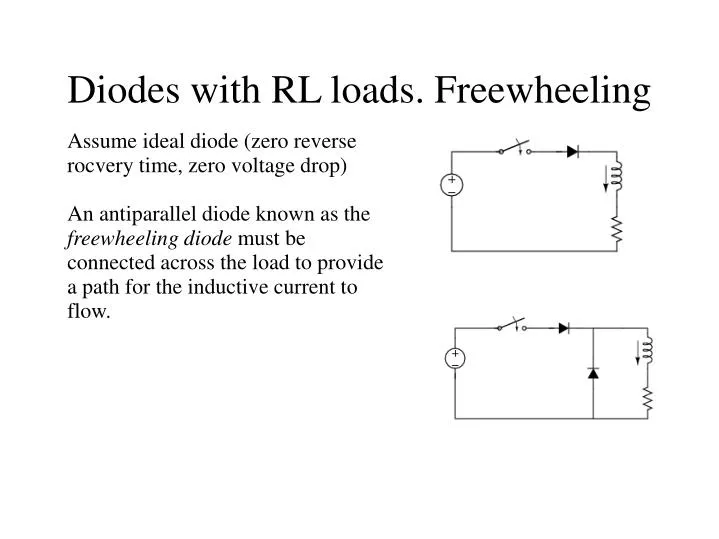
Diodes with RL loads. Freewheeling . Assume ideal diode (zero reverse rocvery time, zero voltage drop) An antiparallel diode known as the freewheeling diode must be connected across the load to provide a path for the inductive current to flow. D1. L. D2. Vs. R. Diode rectifiers.

E N D
Diodes with RL loads. Freewheeling Assume ideal diode (zero reverse rocvery time, zero voltage drop) An antiparallel diode known as the freewheeling diode must be connected across the load to provide a path for the inductive current to flow.
D1 L D2 Vs R Diode rectifiers Learn performance parameters of rectifiers and power converters Study effects of load inductance on load current
Note that the diode conduction time is longer than half-period The waveform is nonsinusoidal but periodic. The diode current is found using the Laplace transform method: From www.powerdesigners.com
Recommended reading • Chapter 1 • Sections 2.10-2.13 and examples in those sections, the rest are optional) • Sections 3.1 to 3.3, example 3.2
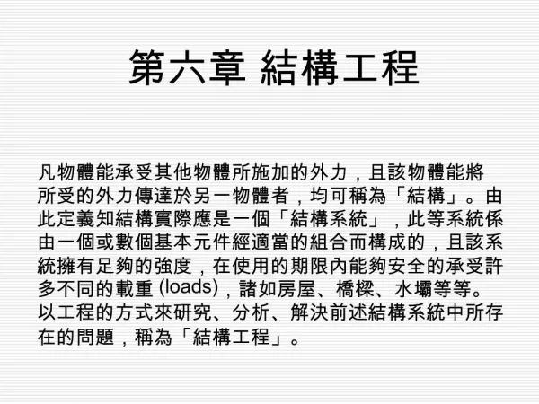
Full wave rectifier with centre tapped transformer Single phase full wave rectifier
For a steady state solution, require i0(0)= i0(T)=I0. Then I0>0 guarantees that the current flows continuously.
Load, source and diode currents (E=10V). Download Matlab code fwr.m, (also requires fun_fwr.m).
Load voltage Source voltage E=120 V Load current
Conclusion • An inductive load can make load current flow continuously if voltage ratio is below the critical value • E=0 guarantees continuous current • If L=0, any E>0 will cause current interruptions • References: Section 3.4 and examples in that section
(Note 30 deg phase shift). -p/6 p/6 0
Performance: Single phase rectifier 3 phase rectifier
Condition for continuous load current Largest critical value of the EMF ratio is substantially higher (95.5% vs 63.6%)