Download
1 / 6
60 likes | 61 Vues
Tunnel Card’s Design Choices. Figure: CFC card top view. Basic components used: Off-the-shelves Current-to-Frequency Converter (x8) Irradiation tests at cyclotrons of Lauvain and PSI Actel FPGA (54SX32A) (x1) 208 pin 32,000 LE One-time-programmable Redundant Inputs

E N D
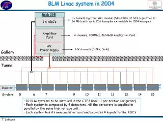
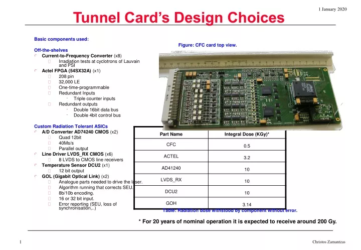
Tunnel Card’s Design Choices Figure: CFC card top view. Basic components used: Off-the-shelves • Current-to-Frequency Converter (x8) • Irradiation tests at cyclotrons of Lauvain and PSI • Actel FPGA (54SX32A) (x1) • 208 pin • 32,000 LE • One-time-programmable • Redundant Inputs • Triple counter inputs • Redundant outputs • Double 16bit data bus • Double 4bit control bus Custom Radiation Tolerant ASICs • A/D Converter AD74240 CMOS (x2) • Quad 12bit • 40Ms/s • Parallel output • Line Driver LVDS_RX CMOS (x6) • 8 LVDS to CMOS line receivers • Temperature Sensor DCU2 (x1) • 12 bit output • GOL (Gigabit Optical Link) (x2) • Analogue parts needed to drive the laser. • Algorithm running that corrects SEU. • 8b/10b encoding. • 16 or 32 bit input. • Error reporting (SEU, loss of synchronisation,..) Table: Radiation dose withstood by component without error. * For 20 years of nominal operation it is expected to receive around 200 Gy. Christos Zamantzas
Mezzanine Cards • Redundant transmission • High radiation tolerance • > 3 KGray • 800 Mbps • Data 640 Mbps • 8bit/10bit encoding • 4 optical diodes • 4 TLK (Texas Instruments) transceivers • 8bit/10bit decoding • Synchronisation • Clock extraction • 1MB non-volatile RAM • Programmable either via FPGA or RJ45 Christos Zamantzas
Error-free Communication The steps taken to ensure a reliable communication link: • Double (redundant) optical link • CRC-32 error check algorithm • All single-bit errors. • All double-bit errors. • Any odd number of errors. • Any burst error with a length less than the length of CRC. • For longer bursts Pr = 1.16415*10-10 probability of undetected error. • 224 bits of data plus 32 bits of CRC remainder = 256 bits. • 8b/10b encoding • Clock data recovery (CDR) - guarantees transition density. • DC-balanced serial stream - ones and zeros are equal/DC is zero. • Error detection – four times more characters. • Special characters used for control – sync, frame. • 256 bits of data are encoded in 320 bits = 64 extra bits. Christos Zamantzas
Steps taken for a Failsafe Tunnel System To ensure Ionisation Chamber connection: • Modulation Tests • Tests initiated when no beam present. • Sine wave checks the connection and the ADC. • Rectangular wave checks the connection and the CFC. To ensure CFC card correct operation: • Constant Current • A current (~10pA) is applied constantly. • Status monitor • High tension check. • Temperature To minimise SEU: • Radiation Tolerant Components • Custom ASICs, • No Configuration Data, • Radiation Qualification. • TMR (triple modular redundancy) • FPGA design tripled and added voting. • Doubled/Tripled I/Os • Tripled Counter inputs. • Doubled Data and Control outputs. Christos Zamantzas
Transmission Check & Tunnel Status At the Surface FPGA: • CRC-32 • Error check / detection algorithm for each of the signals received. • Comparison of the pair of signals. • Signal Select block • Logic that chooses signal to be used • Identifies problematic areas. • Tunnel’s Status Check block • HT, Power supplies • FPGA errors • Temperature Secondary B Signal Primary A Signal (256 bits) (256 bits) Reception ______________ _ _ Tx Check & Signal Choice ______________ _ _ Tunnel Status Check ______________ _ _ Format Data ______________ _ _ Only CRC Only CRC Check CRC Compare Check CRC validity CRCs validity (4 byte) (4 byte) Error Error Error S/W & TTL output Signal Select Error (A or B) Status Error 10-bits Truncate extra/redundant bits (leave 160 bits) DeMux 1 2 3 … 8 Christos Zamantzas
Steps taken for a Failsafe Surface System To ensure a reliable communication link: • Double (redundant) optical link • CRC-32 error check algorithm • All single-bit errors. • All double-bit errors. • Any odd number of errors. • Any burst error with a length less than the length of CRC. • For longer bursts Pr = 1.16415*10-10 probability of undetected error. • 224 bits of data plus 32 bits of CRC remainder = 256 bits. • 8b/10b encoding • Clock data recovery (CDR) - guarantees transition density. • DC-balanced serial stream - ones and zeros are equal/DC is zero. • Error detection – four times more characters. • Special characters used for control – sync, frame. • 256 bits of data are encoded in 320 bits = 64 extra bits. To avoid misplacement of threshold and/or masking table • Card ID • Each tunnel card holds a unique 16bit number • Included with every transmitted frame • Compared with the one loaded together with the tables To avoid loss of data • Frame ID • Surface FPGA checks for missing frames • 16bit Frame ID number increments by one and is included at every transmission To ensure system failures and dump request recognition • Outputs (Beam Dump signals) as frequency • At a dump request, reset, or failure the transmitted frequency will be altered. Christos Zamantzas