Download
1 / 10
100 likes | 400 Vues
VHDL. entity adder is port (a :in bit_vector(7 downto 0); b :in bit_vector(7 downto 0); ci :in bit; s :out bit_vector(7 downto 0); co :out bit); end adder; architecture logic of adder is

E N D
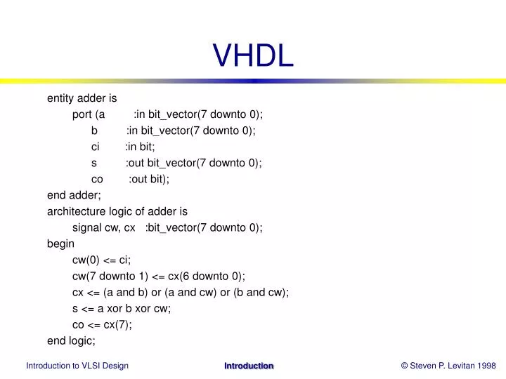
VHDL entity adder is port (a :in bit_vector(7 downto 0); b :in bit_vector(7 downto 0); ci :in bit; s :out bit_vector(7 downto 0); co :out bit); end adder; architecture logic of adder is signal cw, cx :bit_vector(7 downto 0); begin cw(0) <= ci; cw(7 downto 1) <= cx(6 downto 0); cx <= (a and b) or (a and cw) or (b and cw); s <= a xor b xor cw; co <= cx(7); end logic;
VHDL2STDCELL (120) unixs5 % vhdl2stdcell add adder logic -- Pitt/PSU < VHDL > layout tools -- Building adder.logic from file add -- Compiling add.vhdl into add.ivf -- Translating add.ivf into add.glu -- Parsing add.glu into add.eqn -- Use next script: eqn2stdcell add -- All done, logfile is: add.logfile
VHDL2STDCELL (124) unixs5 % eqn2stdcell add -- Another Layout Tool using Standard-Cell Building Chip Layout for add using Std_Cell - running misII phase 1: file format conversion(from Boolean eqn to blif) - running misII phase 2: optimization and technology mapping - running wolfe - running mizer - running octtocif - Running magic to convert cif to magic file -- For more information, read add.makelog
entity mpy is port (a : in bit_vector(1 downto 0); b : in bit_vector(1 downto 0); c : out bit_vector(3 downto 0)); end mpy; architecture logic of mpy is signal temp : bit_vector(3 downto 0); begin temp(3 downto 0) <= a(1 downto 0) & b(1 downto 0); -- with temp(3 downto 0) select c(3 downto 0) <= "0000" when (temp = "0000") else "0000" when (temp = "0001") else "0000" when (temp = "0010") else "0000" when (temp = "0011") else "0000" when (temp = "0100") else "0001" when (temp = "0101") else "0010" when (temp = "0110") else "0011" when (temp = "0111") else "0000" when (temp = "1000") else "0010" when (temp = "1001") else "0100" when (temp = "1010") else "0110" when (temp = "1011") else "0000" when (temp = "1100") else "0011" when (temp = "1101") else "0110" when (temp = "1110") else "1001"; end logic;
Digital Integrated Circuits © Prentice Hall 1995 Introduction
Digital Integrated Circuits © MJ Irwin 1998 The Pennsylvaina State University