Download

1 / 27
270 likes | 475 Vues
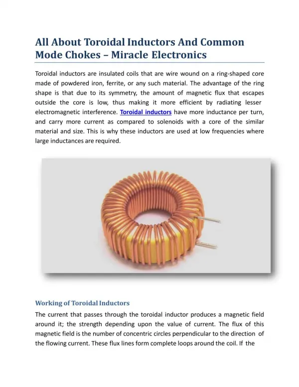
Ferrites and Common-Mode Chokes. Magnetic field tend to concentrate in high- permeability ( 磁導率 ) materials. e.g. The magnetic flux was confined to the ferromagnetic core. Some of the flux leaks out and completes the magnetic path through the surrounding air.

E N D
Magnetic field tend to concentrate in high- permeability(磁導率) materials. • e.g. The magnetic flux • was confined to the • ferromagnetic core. • Some of the flux leaks out and completes the magnetic path through the surrounding air.
The quantity of reluctance(磁阻)R depends on • The permeability of the magnetic path. • Cross-sectional area A • Length l • 用類比lumped circuits 來分析magnetic circuits • Voltage magnetomotive force (mmf) NI • Current magnetic flux
High-permeability core: Rcore << Rair • the majority of the flux confined to the core.
The reluctances of the path the permeablities of the path. The portion of the total flux that remains in the core the ratios of the relative permeablities of the two paths.
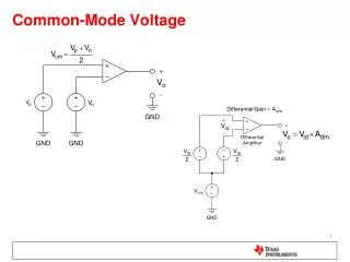
Consider the pair of parallel conductors carring current I1 and I2. Decompose with differential-mode current ID and common-mode current IC. Common-mode & Differential-mode current I1 = IC + ID I2 = ICID ID = 0.5 ( I1I2) IC = 0.5 ( I1+I2)
The differential-mode currents • are equal in magnitude but oppositely directed in the two wires. • The common-mode currents • are equal in magnitude and are directed in the same direction.
The differential-mode current are oppositely directed. The resulting electric field will also be oppositely directed. Two conductors are not collocated. The fields will not exactly cancel. It will subtract to give a small net radiated electric field.
The common-mode currents are directed in the same direction. Their radiated fields will add giving a much larger contribution to the total radiated field than will the differential-mode current.
A pair of wires carrying currents I1 and I2 are wound around a ferromagnetic core. • Calculate the impedance
Consider common-mode currents (I1=IC, I2=IC) ZCM = p (L + M)
Consider differential-mode currents (I1=ID and I2=ID) ZDM = p (L M) If the windings are symmetric and all the flux remains in the core L=M ; ZDM = 0
In the ideal case (L=M) A common-mode choke • has no effect on differential-mode current. • but selectively places an inductance 2L in series with the two conductors to common-mode currents. Thus, common-mode choke can be effective in blocking common-mode currents.
Ferromagnetic materials • ''saturation effect'' at high currents • Their permeabilities tend to deteriorate with increasing frequency. The functional or differential-mode current ID are the desired currents and usually large in magnitude. The common-mode choke • Fluxes (due to high differential-mode currents) cancel in the core. • No saturation.
Ferrite core materials have different frequency responses of their permeability. Typically: MnZn, NiZn
The frequency response of the impedance of a inductor (formed by winding five turns of #20 gauge wire on two toroids) 1 MHz60 MHz MnZn: 500 MnZn: 380 NiZn: 80 NiZn: 1200
Ferrite materials are basically nonconductive ceramic(陶瓷) materials • Ferrite materials can be used to provide selective attenuation(衰減) of high-frequency signals and not affect the more important lower-frequency components of the functional signal.
The most common form of ferrite materials is a bead. • The ferrite material is formed around a wire, so that • the device resembles an ordinary resister.
The ferrite bead can be inserted in series with a wire or land, and provide a high-frequency impedance in that conductor. • The ferrite bead affects both differential- mode and common-mode currents equally. • If the high-frequency components of the differential-mode current are important from a functional standpoint, then the ferrite bead may affect functional performance of the system.
The current produces magnetic flux in the circumferential direction. • This flux passes through the bead material producing an internal inductance. • The inductance the permeability of the bead material Lbead = 0rK • K: const, dep. on the bead dimension
The bead material is characteristized by a complex relative permeability r = 'r(f) j "r(f) • [The real part] 'r is related to the stored magnetic energy in the bead material. • [The imaginary part] "r is related to the losses in the bead material. • 'r & "rboth are functions of frequency.
From this result, the equivalent circuit consists of a resistance (dep. on frequency) in series with an inductance (dep. on frequency)
Typical ferrite beads give impedances of order 100 above 100MHz. • Multiple-hole ferrite beads can be used to increase the high-frequency impedance. • The impedance of ferrite beads is typically used in low-impedance circuits. • Ferrite beads and the other uses of ferrites are susceptible to saturation when used in circuits that pass high-level, low-frequency currents.