Download
1 / 15
160 likes | 1.15k Vues
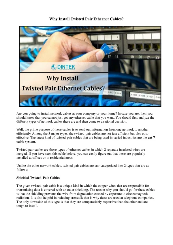
Common Mode Termination Of Ethernet Twisted Pairs. Royce Bohnert. Typical Ethernet Circuit. Diff pairs from RJ45 connect to isolation transformer Diff pairs from transformer connect to Ethernet Phy IC 100 Ω diff pairs are terminated at the Phy. Ethernet Magnetics.

E N D
Common Mode Termination Of Ethernet Twisted Pairs Royce Bohnert
Typical Ethernet Circuit • Diff pairs from RJ45 connect to isolation transformer • Diff pairs from transformer connect to Ethernet Phy IC • 100Ω diff pairs are terminated at the Phy
Ethernet Magnetics • Most Ethernet magnetics come with integrated CM chokes • Transformer center taps provide access to CM signals
Robert Smith Termination Method • US Patent 5321372, Published 6/14/1994 • The combination of pairs within a UTP cable form transmission line • CM currents can flow on these transmission lines, causing radiated emissions
Was Smith Wrong? • Article on EE Times by Jim Satterwhite • Author asserts that Smith was wrong about the value that should be used for the termination. • Presents measurements and claims that the appropriate termination resistance is 52.3Ω
Goal Of This Project • How much of an impact does this termination actually have on radiated emissions? • Marine VHF band (156 – 165 MHz) of particular interest • Evaluated by measuring CM current on cable
Measuring CM Current • RF Current Probe • Solar Electronics Company, Type 9210-1 • 300 KHz -500 MHz • Nominal ZT is 0.3-5Ω. Relates measured voltage to current.
Measuring CM Current • Spectrum Analyzer • Agilent E7402A (EMC Analyzer) • Agilent E4446A
Measurement Setup • RF current probe place on ~20m long cable • Cable connected to a device on each end • Results viewed on spectrum analyzer
CM Current - Results 75 Ohm Termination
CM Current - Results 52.3 Ohm Termination
CM Current - Results No Termination
CM Current - Results • Based on initial results, the termination does not appear to have a significant impact.
Possible Conclusions • CM chokes so effective at reducing CM currents that the effect termination is negligible. • Impedance is not constant along length of cable. Different twist rates on each twisted pair cause cancellation of field every few centimeters.
References • Updating the Bob Smith Termination Technique http://www.eetimes.com/document.asp?doc_id=1277940 • US Patent 5321372, Apparatus and method for terminating cables to minimize emissions and susceptibility • Electromagnetic Compatibility Engineering, Henry W. Ott