Download
1 / 14
150 likes | 493 Vues
Analysis of Intermodulation Distortion in Ferrite Circulators. Anuj Srivastava Karen Kocharyan Presented at MTT-2003 Renaissance Electronics Corporation Harvard, MA. OVERVIEW. Introduction Linearized Equation of Motion for Magnetization Nonlinear Oscillations of Magnetization

E N D
Analysis of Intermodulation Distortion in Ferrite Circulators Anuj Srivastava Karen Kocharyan Presented at MTT-2003 Renaissance Electronics Corporation Harvard, MA
OVERVIEW • Introduction • Linearized Equation of Motion for Magnetization • Nonlinear Oscillations of Magnetization • Nonlinear Model • IMD Data on a PCS Circulator • Summary
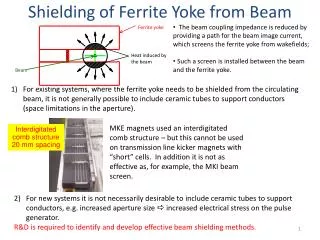
Top Magnet Top Ground plane Ferrite Disc Central Junction H Basic Construction of a Stripline Ferrite Junction Circulator OBSERVATION: As H was increased, 3rd order IMD reduced considerably.
Z mt Mz Ms h Y X Equation of Motion of Magnetization Vector Linear Theory Ho Assuming rf products (hmt) ~ 0
Solution: Ferromagnetic resonance: Solution of Linearized Equation of Motion Assuming harmonic (exp(it)) time dependence of h and mt:
Suscep-tibility , a Internal field (Oe) Tensor Susceptibility vs. Internal Field Below resonance Above resonance a Difference between and a is more in the below resonance than above resonance region
Z Ms T3 T4 T2 T1 h Y X Nonlinear Oscillations of Magnetization • Magnetization vector does not precess in a circular path. • As the rf power is increased, higher order terms become significant and can no longer be neglected. Time derivative of mz is not zero. • Instability in the non-linear motion at high power levels depends on the anisotropy (shape, magneto-crystalline) present in the sample.
2 my0 4 3 2 1 Z 1 3 4 mz @ 2 X Y X Y mx0 my0 mx0 Harmonic Generation Note: Magnetization Ms is held constant
Nonlinear Model • Small signal approximation: • High signal levels (for linearly polarized rf fields):
Final Expression • Harmonics due to mt’s 2 dependence. • When two frequencies co-exists, combined frequencies, 21,2 ± 2,1,develop.
MATCHED LOAD D .U. T. 30 dB coupler SPECTRUM ANALYZER FILTER 40 W GENERATOR (1930 MHz) ISOLATORS 40 W GENERATOR (1990 MHz) ISOLATORS 3 dB POWER COMBINER Experimental Setup
IMD as a function of field offset 3rd order Intermodulation Distortion (dBc) Internal Magnetic Field (Oe)
IMD vs. Bandwidth Bandwidth is Inversely Proportional to the Internal Magnetic Field
Summary • Intermodulation distortion decreases rapidly as operating field is moved away from resonance - valid for both above resonance and below resonance devices. • Above resonance devices should have better IMD performance than below resonance. • Planar anisotropy shall result in higher intermod values with respect to Isotropic conditions.