Download

1 / 28
300 likes | 663 Vues
Finite State Machine (FSM). Nattha Jindapetch December 2008. Agenda. Finite State Machine (FSM) Synthesis techniques Lab5. Finite State Machines. Basically a FSM consists of C o ntrol logic is used to decide the next state of the FSM

E N D
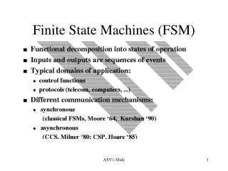
Finite State Machine (FSM) Nattha Jindapetch December 2008
Agenda • Finite State Machine (FSM) • Synthesis techniques • Lab5
Finite State Machines • Basically a FSM consists of • Control logic is used to decide the next state of the FSM • sequential is used to store the current state of the FSM • output logicis a mixture of both comb. and seq. logic • Two types • Moore machine O = f(Q) Q’= f(Q,I) • Mealy machine O = f(Q,I) Q’= f(Q,I)
Example 1 State table State diagram
module jk_counter(count, clock); input clock; output reg [2:0] count; parameter [2:0] A = 3'b000, B = 3'b100, C = 3'b111, D = 3'b010, E = 3'b011; always @ (posedge clock) case (count) A: count <= B; B: count <= C; C: count <= D; D: count <= E; E: count <= A; default: count <= A; endcase endmodule Example 1 State diagram
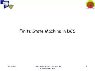
in 0 S0 “out” 1 1 S0 “0” S1 “0” S2 “1” 0 1 0 Symbol State Diagram Ex2: Moore Machines • Check input steam • Ifin = 1 two consecutiveperiods, then out=1
1 S0 “0” 1 S1 “0” S2 “1” 1 0 0 The meaning ofState Diagram • For example, at stateS0 • At stateS0 the circuit outputout = 0 • At the rising-edge ofclk, ifin = 1, the state will change to S1, otherwise S0 0
module Moore1 (clk, IN, OUT); input clk, IN; output OUT; reg [1:0] State; parameter [1:0] s0=2’b00, s1=2’b01, s2=2’b11; always @ (posedge clock) case (State) s0: begin OUT <= 0; if (IN) State <= s1; else State <= s0; end s1: begin OUT <= 0; if (IN) State <= s2; else State <= s0; end s2: begin OUT <= 1; if (!IN) State <= s0; else State <= s2; end default: begin OUT <= 0; if (IN) State <= s1; else State <= s0; endcase endmodule Ex2: Moore Machines
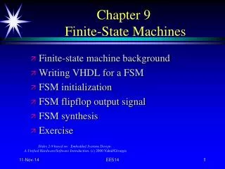
in/out 0/0 S0 1/0 S0 S1 0/0 1/1 Symbol State Diagram Ex3: Mealy Machines • Check input steam • Ifin = 1 two consecutiveperiods, then out=1
0/0 1/0 0/0 S0 S1 1/1 The meaning ofState Diagram • For example, at stateS1 • AtS1, the output OUT = IN (OUT=1 if IN=1 andOUT=0 ifIN=0) • At the rising-edge ofclk, ifIN = 0 the state will change to S0, otherwiseS1
Ex3: Mealy Machines s1: begin OUT <= IN; if (IN) State <= s2; else State <= s0; end default: begin OUT <= 0; if (IN) State <= s1; else State <= s0; end endcase endmodule module Mealy1 (clk, IN, OUT); input clk, IN; output OUT; reg State; parameter s0=1’b0, s1=1’b1; always @ (posedge clock) case (State) s0: begin OUT <= 0; if (IN) State <= s1; else State <= s0; end
Ex4: Arbiter • First come first serve
module fsm_using_function (clock, reset, req_0, req_1, gnt_0, gnt_1); input clock,reset,req_0,req_1; output gnt_0,gnt_1; wire clock,reset,req_0,req_1; reg gnt_0,gnt_1; parameter SIZE = 3 ; parameter IDLE =3'b001, GNT0 = 3'b010,GNT1 = 3'b100; reg [SIZE-1:0] state; wire [SIZE-1:0] next_state; assign next_state = fsm_function(state, req_0, req_1); //----------Function for Control Logic---------- function [SIZE-1:0] fsm_function; input [SIZE-1:0] state ; input req_0 ; input req_1 ; case (state) IDLE : if (req_0 == 1'b1) begin fsm_function = GNT0; end else if (req_1 == 1'b1) begin fsm_function= GNT1; end else begin fsm_function = IDLE; end Ex4_1: Arbiter Code Using A Function for Control Logic(1/3)
GNT0 : if (req_0 == 1'b1) begin fsm_function = GNT0; end else begin fsm_function = IDLE; end GNT1 : if (req_1 == 1'b1) begin fsm_function = GNT1; end else begin fsm_function = IDLE; end default : fsm_function = IDLE; endcase endfunction //----------Seq Logic----------------------------- always @ (posedge clock) begin : FSM_SEQ if (reset == 1'b1) begin state <= #1 IDLE; end else begin state <= #1 next_state; end end Ex4_1: Arbiter Code Using A Function for Control Logic(2/3)
//----------Output Logic------------- always @ (posedge clock) begin : OUTPUT_LOGIC if (reset == 1'b1) begin gnt_0 <= #1 1'b0; gnt_1 <= #1 1'b0; end else begin case (state) IDLE : begin gnt_0 <= #1 1'b0; gnt_1 <= #1 1'b0; end GNT0 : begin gnt_0 <= #1 1'b1; gnt_1 <= #1 1'b0; end GNT1 : begin gnt_0 <= #1 1'b0; gnt_1 <= #1 1'b1; end default : begin gnt_0 <= #1 1'b0; gnt_1 <= #1 1'b0; end endcase end end // End Of Block OUTPUT_LOGIC endmodule // End of Module arbiter Ex4_1: Arbiter Code Using A Function for Control Logic(3/3)
Ex4_2: Arbiter Code Using Two Always Blocks(1/2) module fsm_using_always (clock, reset, req_0, req_1, gnt_0, gnt_1); input clock,reset,req_0,req_1; output gnt_0,gnt_1; wire clock,reset,req_0,req_1; reg gnt_0,gnt_1; parameter SIZE = 3 ; parameter IDLE = 3'b001,GNT0 = 3'b010,GNT1 = 3'b100 ; reg [SIZE-1:0] state; reg [SIZE-1:0] next_state; always @ (state or req_0 or req_1) begin : FSM_CONTROL next_state = 3'b000; case (state) IDLE : if (req_0 == 1'b1) next_state = GNT0; else if (req_1 == 1'b1) next_state= GNT1; else next_state = IDLE; GNT0 : if (req_0 == 1'b1) next_state = GNT0; else next_state = IDLE; GNT1 : if (req_1 == 1'b1) next_state = GNT1; else next_state = IDLE; default : next_state = IDLE; endcase end
Ex4_2: Arbiter Code Using Two Always Blocks(2/2) //----------Seq Logic- always @ (posedge clock) begin : FSM_SEQ if (reset == 1'b1) state <= #1 IDLE; else state <= #1 next_state; end //----------Output Logic--------------- always @ (posedge clock) begin : OUTPUT_LOGIC if (reset == 1'b1) begin gnt_0 <= #1 1'b0; gnt_1 <= #1 1'b0; end else begin case (state) IDLE : begin gnt_0 <= #1 1'b0; gnt_1 <= #1 1'b0; end GNT0 : begin gnt_0 <= #1 1'b1; gnt_1 <= #1 1'b0; end GNT1 : begin gnt_0 <= #1 1'b0; gnt_1 <= #1 1'b1; end default : begin gnt_0 <= #1 1'b0; gnt_1 <= #1 1'b0; end endcase end end // End Of Block OUTPUT_LOGIC endmodule // End of Module arbiter
Ex4_3: Arbiter Code Using Single Always For Sequential, Control Logic And Output Logic(1/2) module fsm_using_always (clock, reset, req_0, req_1, gnt_0, gnt_1); input clock,reset,req_0,req_1; output gnt_0,gnt_1; wire clock,reset,req_0,req_1; reg gnt_0,gnt_1; parameter SIZE = 3 ; parameter IDLE = 3'b001,GNT0 = 3'b010,GNT1 = 3'b100 ; reg [SIZE-1:0] state; reg [SIZE-1:0] next_state; always @ (posedge clock) begin : FSM if (reset == 1'b1) begin state <= #1 IDLE; gnt_0 <= 0; gnt_1 <= 0; end else case (state) IDLE : if (req_0 == 1'b1) begin state <= #1 GNT0; gnt_0 <= 1; end else if (req_1 == 1'b1) begin gnt_1 <= 1; state <= #1 GNT1; end else state <= #1 IDLE;
Ex4_3: Arbiter Code Using Single Always For Sequential, Control Logic And Output Logic(2/2) GNT0 : if (req_0 == 1'b1) begin state <= #1 GNT0; end else begin gnt_0 <= 0; state <= #1 IDLE; end GNT1 : if (req_1 == 1'b1) begin state <= #1 GNT1; end else begin gnt_1 <= 0; state <= #1 IDLE; end default : state <= #1 IDLE; endcase end endmodule // End of Module arbiter
Hierarchical Design • Using Hierarchy leads to greater design readability, reuse, and debug Top-Level Control Datapath Memory FSM1 FSM2 ROM RAM ALU Counters Regs
Benefits of Using Hierarchy • Design readability • Easier to understand the design functionality and data flow • Easier to debug • Easy to reuse parts of a design
Coding Tips • Synchronous reset—better system controlbut depend on the circuit behavior • Asynchronous Reset always @(posedge CLOCK or posedge RESET) if (RESET) Q = 0; else Q = D_IN; • Synchronous Reset always @(posedge CLOCK) if (RESET) Q = 0; else Q = D_IN;
Coding Tips • Order and group arithmetic and logical functions and operators A <= (B + C) + (D + E); is better than A <= B + C + D + E;
Basic Performance Tips • Simple coding yields better performance • Avoid high-level loop constructs • Synthesis tools may not produce optimal results • Avoid nested if-then-else statements • Most tools implement these in parallel; however, multiple nested if-then-else statements can result in priority encoded logic • Use case statements for large decoding • Rather than if-then-else
State Machine Encoding • Use enumerated types to define state vectors • Most synthesis tools have commands to extract and re-encode state machines described in this way • Use one-hot encoding for high-performance state machines • Uses more registers, but simplifies next-state logic • Experiment to discover how your synthesis tool chooses the default encoding scheme
Lab5: FSM for display scan Four 7-segment Digits share the same data bus
State0 D=1110 sel=00 Reset State1 D=1101 sel=01 State2 D=1011 sel=10 Lab5: FSM for display scan State3 D=0111 sel=11