Download
1 / 23
470 likes | 1.35k Vues
KINEMATIC COUPLINGS. The good, the bad, the ugly…. Defining constraint. Clever use of constraint. Penalties for over constraint. Exact Constraint: Number of constraint points = DOF to be constrained These constraints must be independent!!!

E N D
KINEMATIC COUPLINGS The good, the bad, the ugly….
Defining constraint Clever use of constraint Penalties for over constraint
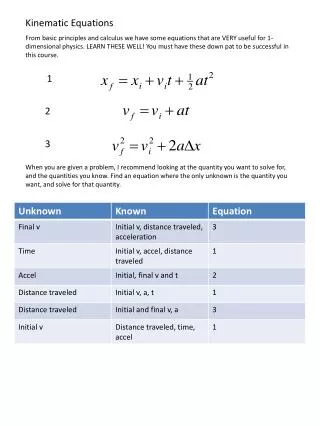
Exact Constraint: Number of constraint points = DOF to be constrained These constraints must be independent!!! Assuming couplings have rigid bodies, equations can be written to describe movements Design is deterministic, saves design and development $ KCs provide repeatability on the order of parts’ surface finish ¼ micron repeatability is common Managing contact stresses are the key to success Exact constraint (Kinematic) design
Making life easier • “Kinematic Design”, “Exact Constraint Design”…..the issues are: • KNOW what is happening in the system • Manage forces and deflections • Minimize stored energy in the coupling • Know when “Kinematic Design” should be used • Know when “Elastic Averaging” should be used (next week) Picture from Precision Machine Design, Slocum, A. H. Kelvin Clamp Boyes Clamp
Accuracy Repeatability Accuracy & Repeatability Kinematic couplings • Kinematic Couplings: • Deterministic Coupling • # POC = # DOF • Do Not Allow Sealing Contact • Excellent Repeatability • Performance • Power of the KC
Geometry Material ni Applied Loads [Fp & Mp] Interface Forces [Fi] Deflections d -> Dr Relative Error Kinematic Coupling Groove Mating Spherical Element Contact Force Coupling Centroid Angle Bisectors Coupling Triangle Modeling Kinematic coupling error motions 6 Unknown Forces & 6 Equilibrium Equations S Fi = FP S Mi = MP Hertzian Point Contact for Local Displacements di = f(EB, EG, nB, nG, RB, RG)
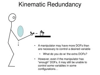
KC error motion analysis • Need dx, dy, dz, ex, ey , ez to predict effect of non-repeatability • Hertz deflections -> displacements of ball centers • Three ball centers form a plane • Analyze relative position of “before” and “after” planes for error motions B1 B3 B2 Original Positions Final Positions
l qc n Point A Initial Position of Ball’s Far Field Point dr dl Contact Cone dz Initial Contact Point dn Final Position of Ball’s Far Field Point Initial Position of Groove’s Far Field Point z Point B Final True Groove’s Far Field Point r Max t Final Contact Point Kinematic couplings and distance of approach • How do we characterize motions of the ball centers? • dn = distance of approach Max shear stress occurs below surface, in the member with larges R
Contact mechanics – Hertzian contact • Heinrich Hertz – 1st analytic solution for “near” point contact • KC contacts are modeled as Hertz Contacts • Enables us to determine stress and distance of approach, dn Radii F Load D = 2 dn Modulus F n Ratio Stress Deflection
Key Hertzian physical relations • Equivalent radius and modulus: • cos(q) function (f is the angle between the planes of principal curvature of the two bodies) • Solution to elliptic integrals estimated with curve fits
KEY Hertzian relation scaling laws • Contact Pressure is proportional to: • Force to the 1/3rd power • Radius to the –2/3rd power • Modulus to the 2/3rd power • Distance of approach is proportional to: • Force to the 2/3rd power • Radius to the –1/3rd power • Modulus to the –2/3rd power • Contact ellipse diameter is proportional to: • Force to the 1/3rd power • Radius to the 1/3rd power • Modulus to the –1/3rd power • DO NOT ALLOW THE CONTACT ELLIPSE TO BE WITHIN ONE DIAMETER OF THE EDGE OF A SURFACE!
Calculating error motions in kinematic couplings • Motion of ball centers -> Centroid motion in 6 DOF -> Dx, Dy, Dz at X, Y, Z • Coupling Centroid Translation Errors • Rotations • Error At X, Y, Z (includes translation and sine errors)
Kinematic coupling centroid displacement Picture from Precision Machine Design, Slocum, A. H.
General design guidelines • Location of the coupling plane is important to avoid sine errors • For good stability, normals to planes containing contact for vectors should bisect angles of coupling triangle • Coupling triangle centroid lies at center circle that coincides with the three ball centers • Coupling centroid is at intersection of angle bisectors • These are only coincident for equilateral triangles • Mounting the balls at different radii makes crash-proof • Non-symmetric grooves make coupling idiot-proof
Kinematic coupling stability theory, instant centers Poor Design Good Design Picture from Precision Machine Design, Slocum, A. H. *Pictures courtesy Alex Slocum Precision Machine Design
Sources of errors in kinematic couplings Thermal Errors Surface Finish Geometry Disturbance Material Property Disturbance Displacement Disturbance Coupling System Kinematics Material • Inputs • Force • Displacement • Desired Outputs • Desired Location Geometry Others Force Disturbance Error • Actual Outputs • Actual Location Error Loads Preload Variation
Problems with physical contact (and solutions) • Surface topology (finish): • 50 cycle repeatability ~ 1/3 mm Ra • Friction depends on surface finish! • Finish should be a design spec • Surface may be brinelled if possible • Wear and Fretting: • High stress + sliding = wear • Metallic surfaces = fretting • Use ceramics if possible (low m and high strength) • Dissimilar metals avoids “snowballing” • Friction: • Friction = Hysteresis, stored energy, over constraint • Flexures can help (see right) • Lubrication (high pressure grease) helps • Beware settling time and particles • Tapping can help if you have the “magic touch” A A B B l l Mate n Mate n + 1 Wear on Groove Picture from:Schouten, et. al., “Design of a kinematic coupling for precision applications”, Precision Engineering, vol. 20, 1997. Ball in V-Groove with Elastic Hinges
Experimental results – Repeatability & lubrication Slocum, A. H., Precision Engineering, 1988: Kinematic couplings for precision fixturing – Experimental determination of repeatability and stiffness Radial Repeatability (Unlubricated) 2 Displacement, mm 0 600 Number of Trials Radial Repeatability (Lubricated) 2 Displacement, mm 0 600 Number of Trials
Practical design of kinematic couplings • Design • Specify surface finish or brinell on contacting surfaces • Normal to contact forces bisect angles of coupling triangle!!! • Manufacturing & Performance • Repeatability = f (friction, surface, error loads, preload variation, stiffness) • Accuracy = f (assembly) unless using and ARKC • Precision Balls (ubiquitous, easy to buy) • Baltec sells hardened, polished kinematic coupling balls or….. • Grooves (more difficult to make than balls) • May be integral or inserts. Inserts should be potted with thin layer of epoxy • Materials • Ceramics = low friction, high stiffness, and small contact points • If using metals, harden • Use dissimilar materials for ball and groove • Preparation and Assembly • Clean with oil mist • Lubricate grooves if needed
Example: Servo-controlled kinematic couplings • Location & automatic leveling of precision electronic test equipment • Teradyne has shipped over 500 systems • Ph.D. Thesis: Michael Chiu
Example: Canoe-Ball kinematic interface element • The “Canoe Ball” shape is the secret to a highly repeatable design • It acts like a ball 1 meter in diameter • It has 100 times the stiffness and load capacity of a normal 1” ball • Large, shallow Hertzian zone is very (i.e. < 0.1 microns) repeatable • M.S. Thesis, Bernhard Muellerheld
Canoe-Ball repeatability measurements Test Setup 0.1 mm Coupling -0.2 mm 0.1 mm Meas. system -0.1 mm
There are MANY uses for Kinematic Couplings…. • The Kinematic Sheet Coupling was created for the PCB industry • It provides 10x greater repeatability than traditional 4 pins-in-4-slots method