Download
1 / 30
560 likes | 1.34k Vues
Kinematic Design. Mark Sullivan September 11, 2008. Agenda. Review Introduction Kinematic Constraint / Exact Constraint Constraint Line Instantaneous Center of Rotation Axes of Rotation Constraining Rotational Motion Equivalent Sets of Constraints Table of Orthogonal Constraints

E N D
Kinematic Design Mark Sullivan September 11, 2008
Agenda • Review • Introduction • Kinematic Constraint / Exact Constraint • Constraint Line • Instantaneous Center of Rotation • Axes of Rotation • Constraining Rotational Motion • Equivalent Sets of Constraints • Table of Orthogonal Constraints • Blade Flexures • Wire Flexures • Kinematic Coupling • Summary • References
Review: Scale Powers of 10
Pop Quiz: The Size of Things • Always a good idea to have a physical feel for the size of things • The thickness of this paper = • The diameter of a human hair = • Computer hard drive track spacing = • Diameter of a fiber optic = • Visible light wavelength (mid-spectrum) = • Size of a typical virus = • Atomic diameter = 100 μm 20 – 180 μm 1 μm 4 or 62.5 μm core, 125 μm cladding 550 nm 10 – 400 nm 0.1 – 0.6 nm (He to Cs)
Introduction • Machines and instruments are made up of elements that are suitably arranged and many of which that are movably connected. • Two parts that are in contact and move relative to one another are called kinematic “pairs” or can be thought of as being kinematically coupled. • Sliding, rotating, or helical motion (screwing) are “lower” pairs • Other combinations of the above are “higher” pairs • A connection between two pairs is a “link” • Any “rigid body” in free space has six degrees of freedom. • 3 translations • 3 rotations • Can resolve any motion of the rigid body into translations parallel to coordinate axes and rotations around these axes. • Non-rigidity adds extra degrees of freedom
Introduction (2) • The number of contact points between any two rigid bodies is equal to the number of their mutual constraints. • Examples: • Sphere on a plane • One contact point • Motion with respect to plane is constrained in z • Sphere in a trihedral hole • Three points in contact • Three translations are constrained • Others: • See Smith & Chetwynd, p. 49 • How should I constrain a body to have zero degrees of freedom? • Provide six contact points • Ex: Smith & Chetwynd, p. 52 • Bear in mind that we can come up with geometric singularities that degenerate and allow degrees of freedom.
Introduction (3) • Sphere on a Flat Plate:
Kinematic Constraint Kinematics: Study of geometry of motion Kinetics: Study of forces involved Kinematics: Deals with idealized concepts such as point contacts applied to the analysis of rigid body mechanisms. Kinematic constraint: Concerned with the number of degrees of freedom (DOF) possessed by a mechanism geometry. - Smith & Chetwynd, 1992 If the degree of constraint does not exactly match the required freedom, it is unlikely that the design will function as expected.
Exact Constraint By “dusting off” the principles of kinematics and applying them to machine design, we arrive at the method of Exact Constraint. The method of Exact Constraint has been developed to the point where it comprises a body of knowledge which can be used to routinely create new machine designs which are both high in performance and low in cost. The results are so excellent, yet so obvious; so elegant, yet so simple; that at once they seem both profound and trivial! Perhaps it is this duality which has kept these principles so well hidden. One may ask: “Of what value could anything so trivial be?” And so these principles have been overlooked. They have become disused. - Douglass Blanding, 1992
Kinematic Design in Precision Engineering • Mechanism designers routinely use the principles of kinematics because overconstrained and underconstrained devices simply will not function. • Note to Precision Engineers: At some scale, everything is a mechanism. • The component that must remain stable to nanometers will not if it is overconstrained to a structure that deforms by micrometers. ( Isolate structural loop from metrology loop!)
The Constraint Line& Equivalent Constraints • Statement 1: Points on the object along the constraint line can move only at right angles to the constraint line, not along it. • Statement 2: Any constraint along a given constraint line is functionally equivalent to any other constraint along the same constraint line (for small motions).
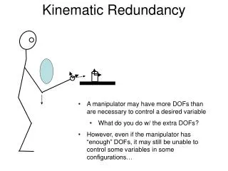
Instantaneous Center of Rotation(Instant Center) • Statement 3: Any pair of constraints whose constraint lines interact at a given point, is functionally equivalent to any other pair in the same plane whose constraint lines intersect at the same point. This is true for small motions and where the two constraints lie on distinctly different constraint lines.
Exercise 1 A ladder is constrained by a vertical wall and a horizontal floor. On the sketch, show the instant center. Also show the path of the instant center for the ladder between the extreme positions, that is, vertical and horizontal. What geometric shape is the path?
Axes of rotation intersectall constraints • Statement 4: The axes of a body’s rotational degrees of freedom will each intersect all constraints applied to the body.
Constraining Rotational Motion • Statement 5: A constraint applied to a body removes that rotational degree of freedom about which it exerts a moment.
Equivalent Sets of Constraints • Statement 6: Any set of constraints whose constraint lines intersect a complete and independent set of rotational axes, is functionally equivalent to any other set of constraints whose constraint lines intersect the same or equivalent set of rotational axes. This is true for small motions and when each set contains the same number of independent constraints.
Exercise 2 The three constraints in the figure allow rotation about three non-intersecting axes. Draw in the three axes (hint: use Statement 4).
Blade Flexures • Statement 7: An ideal blade flexure imposes absolutely rigid constraint in its own plane (x, y, & θz), but it allows three degrees of freedom: z, θx, &θy.
Wire Flexures • Statement 8: An ideal wire flexure imposes absolutely rigid constraint along its axis (x), but it allows fived degrees of freedom: y, z, θx, θy, &θz. An example of three wire flexures arranged to form a pivot flexure. Notice that the wires do not intersect. This causes coupled motion between rotation and translation like a screw.
Kinematic Coupling • We will most often be interested in couplings that allow zero DOF (also called clamps or mounts) and 1 DOF (slides, ways, bearings). • What happens if more constraints are introduced than are necessary? • Overconstraint subject to internal stress, hence strain • Redundant constraint 4-legged stool vs. 3-legged stool • Four key problems: • Non-repeatable relative motions between elements and/or repositioning capability (ex. 3 vs. 4-legged stool) • Transmission of distortion • Inability to accommodate relative thermal dimensional changes without causing internal stresses and strains • Generally higher accuracy of construction and assembly required, hence higher cost to achieve comparable levels of performance.
Kinematic Coupling (2) • Why? • Hold two bodies without motion and avoid problems of overconstraint or redundant constraint. • Allow bodies to be separated and rejoined with high degree of repeatability. • Optical mounts • Kelvin clamp (cone, vee, flat) insensitive to thermal changes • Alternate with 3 vees • Additional way to make trihedral hole • 3-ball nest • machined version • Note: There are degenerate cases • 3 vees tangent to a circle • cone-vee-slot, where cone lies on normal to slot • See Braddick, p. 66 • Constraining surface should be put normal to displacement vector that could take place at that point without violating the other constraints if the surface were removed.
Kinematic Coupling (3) • Kinematic coupling provide a rigid, repeatable connection between two objects.
Kinematic Coupling (4) • Variations on the basic three-vee configuration may be considered to better suit the application.
Kinematic Coupling (5) • Modified 3-Vee Coupling
Kinematic Coupling (6) From Hale, 1999
Kinematic Design Summary • Degrees of Freedom and constraints • The number of contact points between determines the number of constraints • Be careful with degenerate configurations of contacts • Ex: Degenerate Kelvin clamp • Couplings of zero DOF 6 contact points • Couplings of one DOF 5 contact points • Kinematic design • Design mating components so that they impose only the necessary and sufficient constraints for the desired effect. • Why? • To minimize non-repeatable relative motions between elements or non-repeatable assembly • To minimize transmission of distortion • To minimize effects of thermal dimensional changes • To minimize required accuracy of parts and construction to achieve performance goals.
Kinematic Design Summary (2) • Semi-Kinematic Design • Apply principles of kinematic design • Theoretical point contacts are expanded into lines and/or surfaces • Needed when loads are large and point contacts would result in too high stresses • Ex. Slideway design where point supports have been replaced by pad supports.
References • Blanding, D., Exact Constraint: Machine Design Using Kinematic Principles, ASME Press, New York, 1999. • Hale, L. C., “Precision Engineering Principles,” ASPE Tutorial, Monterey, 2006. • Smith, S. T., Chetwynd, D. G., Foundations of Ultraprecision Mechanism Design, Taylor & Francis, 1994. • Hale, L. C., “Principles and Techniques for Designing Precision Machines,” UCRL-LR-133066, Lawrence Livermore National Laboratory, 1999. (http://www.llnl.gov/tid/lof/documents/pdf/235415.pdf) • Furse, J. E., “Kinematic Design of Fine Mechanisms in Instruments,” J. Phys. E: Sci. Instrum., vol. 14, 1981, p. 264-272. • Braddick, H. J. J., The Physics of Experimental Method, Chapman and Hall, London, 1966.