Download
1 / 18
180 likes | 374 Vues
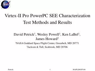
Virtex-II Pro SEE Test Methods and Results. David Petrick 1 , Wesley Powell 1 , James Howard 2 1 NASA Goddard Space Flight Center, Greenbelt, MD 20771 2 Jackson & Tull, Seabrook, MD 20706. Abstract.

E N D
Virtex-II Pro SEE Test Methods and Results David Petrick1, Wesley Powell1, James Howard2 1NASA Goddard Space Flight Center, Greenbelt, MD 20771 2Jackson & Tull, Seabrook, MD 20706 Petrick_P226
Abstract The Xilinx Virtex-II Pro is a platform FPGA that embeds multiple microprocessors within the fabric of an SRAM-based reprogrammable FPGA. The variety and quantity of resources provided by this family of devices make them very attractive for spaceflight applications. However, these devices will be susceptible to single event effects (SEE), which must be mitigated. To use the Virtex-II Pro reliably in space applications, these devices must first be tested to determine if they are susceptible to single event latchup (SEL), the degree to which they are susceptible to single event upsets (SEU) and single event transients (SET), and how these effects are manifested in the device. With this information, mitigations schemes can be developed and tested that address the specific susceptibilities of these devices. This initial SEE test uses a commercial off the shelf Virtex-II Pro evaluation board, with a single processor XC2VP7 FPGA. The FPGA on this board is an acid etched device, which can be partially covered with a shield. The shield covers a portion of the logic, routing, and memory resources along with some of the RocketIO transceivers. The processor, along with a large portion of logic, routing, memory, and transceivers are left exposed. This test will be performed at the Cyclotron Laboratories at Texas A&M University and Michigan State University using ions of varying energy levels and fluencies. Petrick_P226
Virtex-II Pro FPGA XC2VP7-FG456 • 0.13μm CMOS Process • VCCINT: 1.5V • 4.4 Mb Configuration Memory • 1 PowerPC 405 Processor • 8 RocketIO Tranceivers • 44 18x18 Multipliers • 44 18Kb Block RAM • 4 DCMs Virtex-II Pro acid etched to expose die and MGTs Petrick_P226
Memec Test Board 2 Test MGTs RS-232 Virtex-II Pro Custom RS-422 Circuitry P160 Daughter Card JTAG Port Parallel 4 Cable Port Petrick_P226
Radiation Test Details • Testing performed at the Cyclotron labs at Texas A&M and Michigan State Universities • Tested 3 identical boards, each populated with a delidded Virtex-II Pro FPGA • Beam info • Ions: Ar, Kr, Ne, Xe, Cu • Flux: 2.5E2 – 3.2E5 • LET: 2.8 – 53.9 MeV-cm2/mg • Initial testing focus: SEL, SEFI, SEU Petrick_P226
Test Procedure • Shield selected logic with custom brass mask • Program FPGA via PROM or JTAG • Record strip chart power data through GPIB • Record logic mismatch error counter data through RS-422 • Record custom PowerPC/MGT data through RS-232 • Upon device upset, document how communication is reestablished with the FPGA in following order: • Software Reset • Hardware Reset • Reprogram FPGA • Cycle FPGA Power • Record number of configuration bit upsets via iMPACT • Conduct multiple runs using all boards and variety of LET • Record data with and without PowerPC instantiated in design Petrick_P226
Test Setup Diagram Petrick_P226
FPGA Test Design • SEU Detection Logic • ‘Logic Block’ units are identical • ‘Logic Block’ contents: 18x18 Mult, 1024x18 BRAM, 512x1 DFF Shift Reg, 256x4 SRL Shift Reg • ‘Logic Block B’ exposed to radiation • PC counts logic miscompares • Xilinx BERT Application • 2 MGTs in loopback (tx -> rx) • PRS data drives MGT tx pins • PowerPC reports MGT status to PC via RS-232 port Shielded Logic PRS Data Generator Logic Block A Logic Block B Error Comp Block RS-422 to PC Petrick_P226
Device Shielding Techniques Virtex-II Pro Design Floorplan Brass Mask Placement Test MGTs Exposure of PowerPC, Logic Block B, & 1 MGT Isolated Logic Block B for Radiation Exposure Xilinx BERT Logic & Shielded SEU Logic PowerPC Core Isolation of 1 MGT Miscellaneous Logic Petrick_P226
SEFI Data Petrick_P226
SEE Data – MGT Bit Errors Petrick_P226
SEE Data – Configuration Upsets Petrick_P226
Constant Current Ramping • Observations initially made when die was fully exposed during latch-up testing • Ramp rate a function of radiation characteristics, logic usage, and die exposure • Device either reconfigures or causes power-on reset (?) • Current ramps from nominal ICC and ~ 3.3A, ICC then drops to 0A, device reloads configuration bringing ICC back up to nominal where it continues to ramp • Not a function of Over Current Protection setting (unless OCP < 3.3A, then current cycles at this limit) • Does not occur when FPGA irradiated without initially loading configuration file Petrick_P226
Constant Current Plots Device reprograms Note the increased ramp rate Petrick_P226
Conclusions • No destructive SEL event observed to a LET of 53.9 MeV-cm2/mg and a fluency of 107 Ions/cm2 • (Preliminary) The configuration memory and PowerPC have high susceptibility to radiation • 400,000+ configuration errors recorded during two short runs • SEFIs occurred too quickly to collect enough data on the PowerPC • Action required to reestablish device functionality • Reprogram: 70%, Software Reset: 28%, Power Cycle: 2% • Other observations • Jumps in the PowerPC instruction set • Lost JTAG capability twice during SEL testing • Cyclical current ramping • PowerPC reset itself twice during tests Petrick_P226
Lessons Learned • Hard to extract valid data from ‘SEU Detection Logic’ due to the quick accumulation of configuration bit upsets • Consider board with SelectMAP port to allow scrubbing • Acid etching delidding process is very difficult with this package • Consider flip-chip package in conjunction with a socketed board • Must use microscope when performing mask alignment • Misplaced mask caused unexpected SEEs Petrick_P226
Future Work • Continue radiation testing to gather detailed data to support conclusions on each device failure event • Various iterations with different logic architectures which focus on different elements of the Virtex-II Pro • Tailor tests to allow changes in clock frequency and temp • Research SEU mitigation techniques • Xilinx TMR tool • Partial reconfiguration (scrubbing) • Use of redundant MGTs and PowerPCs with voting circuitry Petrick_P226
Acronym List • BERT: Bit Error Rate Test • DCM: Digital Clock Manager • LET: Linear Energy Transfer • MGT: Multi-Gigabit Transceiver • SEE: Single Event Effect • SEFI: Single Event Functional Interrupt • SEL: Single Event Latch-up • SEU: Single Event Upset • TMR: Triple Modular Redundancy Petrick_P226