Download
1 / 87
880 likes | 1.08k Vues
Virtex II Pro based SoPC design. Part 2 Advanced. Before we start …. The guidance consists of two parts: Introduction SoPC concept Working platforms Design Flow – building basic system Advanced topics Adding user cores JTAG Debug Simulation Demonstration. Today. Outline.

E N D
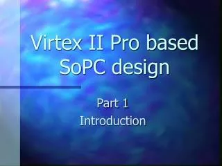
Virtex II Pro based SoPC design Part 2 Advanced
Before we start… • The guidance consists of two parts: • Introduction • SoPC concept • Working platforms • Design Flow – building basic system • Advanced topics • Adding user cores • JTAG • Debug • Simulation • Demonstration Today
Outline • SoPC architecture – review • PLB bus • OPB bus • Adding user cores • Adding cores without a bus • IPIF architecture • Adding cores to OPB and PLB buses • JTAG port • Hardware and Software debug • Hardware debugger – Chip Scope Pro • Software debugger – XMD • Demonstration
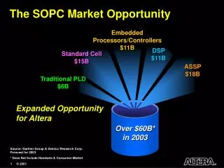
SoPC architecture • Processor Local Bus (PLB) • 32-bit address, 64-bit data • Separate read and write buses • High performance • Low load • On-Chip peripheral bus (OPB) • 32-bit address, 32-bit data • Max peripherals • High load • Device Control Register bus (DCR) • 32-bit transfer to and from GPR • Direct accessible by PPC
PLB bus • 64 bit data / 32 bit address configuration • Up to 16 masters and slaves • Decoupled address, read data, and write data buses • Concurrent read and write transfer • Address pipelining that reduces bus latency by overlapping a new write request with an ongoing write transfer and up to three read requests with an ongoing read transfer • Four priority levels for master requests • Byte-enable capability, supporting unaligned transfers
PLB busarchitecture • Each master has its own data read, write and address bus (all merged to wide buses) • All slaves have shared write data and address bus • Each slave has its own read data bus • All slaves’ read data buses are merged to one wide bus (OR instead of merge in IBM implementation)
PLB bus master attachment PLB arbiter PLB Master [n] Arbitration signals M_BE [n*8:n*8+7] M_ABus [n*32:n*32+31] M_wrDBus [n*64:n*64+63] PLB_MRdDBus [n*64:n*64+63] • Naming conventions: • Each signal from arbiter to master starts from “PLB” • Each signal from master to arbiter starts from “M”
PLB bus slave attachment PLB arbiter PLB Slave [m] PLB_ABus [0:31] PLB_wrDBUS [0:63] Sl_rdDBus [m*64:m*64+63] • Naming conventions: • Each signal from arbiter to slave starts from “PLB” • Each signal from slave to arbiter starts from “Sl”
OPB bus • Actually, AND-OR interconnect structure (distributed multiplexer) • 8-128 bit data / 16-32 bit address configuration • Bus arbitration overlapped with last cycle of bus transfers • 16 masters and unlimited number of slaves • 8-64-bit slaves and 32-64-bit masters • Dynamic bus sizing: byte, halfword, fullword, and doubleword transfers • Optional Byte Enable support • Single cycle transfer of data between OPB bus master and OPB slaves
OPB busarchitecture • Each master has its own read data and address bus (all ORed to single buses) • Each slave has its own read data bus (all ORed with masters’ read data bases to single bus) • ORed masters’ and slaves’ data buses represents shared OPB write data bus OPB_DBus
OPB bus master attachment OPB bus logic OPB Master [n] Mn_BE [0:7] Mn_DBus [0:63] Mn_ABus [0:31] OPB_DBus [0:63] • Naming conventions: • Each signal from bus logic to master starts from “OPB” • Each signal from master to bus logic starts from “Mn”
OPB bus slave attachment OPB bus logic OPB Slave [m] OPB_ABus [0:31] Sln_DBUS [0:63] OPB_DBus [0:63] • Naming conventions: • Each signal from bus logic to slave starts from “OPB” • Each signal from slave to bus logic starts from “Sln”
Adding user logic to design Question: How user logic is added to design? Choose chip with required hard cores inside Add required soft cores Answer : user cores creation Add user logic • EDK can only recognize logic organized in a form of core
User core directory structure Usually this directory structure is created automatically by “Import peripheral Wizard”! Project root directory pcores <User-core-name_version> data devl hdl netlist doc “mpd” file “pao” file “bbd” file vhdl verilog Optional
User core directory structure • Data directory contains EDK interface files for the core: • “mpd” file –Microprocessor Peripheral Description • “pao” file –Peripheral Analyze Order • “bbd” file –Black Box Definition • HDL directory contains HDL (VHDL or Verilog) files representing the core • Netlist directory contains synthesized netlists added as a part of core (not always all the core is written in HDL) • Doc directory contains documentation of the peripheral • Devl directory contains different files created by “Import Peripheral Wizard” Press to see example Press to see example Press to see example
MPD file • MPD file defines the interface of the peripheral • MPD includes: • List of ports and default connectivity for bus interfaces • List of parameters and default values • Any MPD parameter is overwritten by the equivalent MHS assignment
MPD file - example BEGIN opb_gpio ## Peripheral Options OPTION IPTYPE = PERIPHERAL OPTION IMP_NETLIST = TRUE OPTION SIM_MODELS = BEHAVIORAL:STRUCTURAL ## Bus Interfaces BUS_INTERFACE BUS=SOPB, BUS_STD=OPB, BUS_TYPE=SLAVE ## Generics for VHDL or Parameters for Verilog PARAMETER C_BASEADDR=0xFFFFFFFF, DT=std_logic_vector, MIN_SIZE=0x100, BUS=SOPB PARAMETER C_HIGHADDR=0x00000000, DT = std_logic_vector, BUS=SOPB PARAMETER C_OPB_DWIDTH=32, DT=integer, BUS=SOPB PARAMETER C_OPB_AWIDTH=32, DT=integer, BUS=SOPB PARAMETER C_GPIO_WIDTH=32, DT=integer PARAMETER C_ALL_INPUTS=0, DT=integer ## Ports PORT OPB_Clk = “”, DIR=IN, SIGIS=CLK, BUS=SOPB PORT OPB_Rst = OPB_Rst, DIR=IN, BUS=SOPB PORT OPB_ABus = OPB_ABus, DIR=IN, VEC=[0:C_OPB_AWIDTH-1], BUS=SOPB PORT OPB_BE = OPB_BE, DIR=IN, VEC=[0:C_OPB_DWIDTH/8-1], BUS=SOPB PORT OPB_DBus = OPB_DBus, DIR=IN, VEC=[0:C_OPB_DWIDTH-1], BUS=SOPB PORT OPB_RNW = OPB_RNW, DIR=IN, BUS=SOPB PORT OPB_select = OPB_select, DIR=IN, BUS=SOPB PORT OPB_seqAddr = OPB_seqAddr, DIR=IN, BUS=SOPB PORT GPIO_DBus = Sl_DBus, DIR=OUT, VEC=[0:C_OPB_DWIDTH-1], BUS=SOPB PORT GPIO_errAck = Sl_errAck, DIR = OUT, BUS=SOPB PORT GPIO_retry = Sl_retry, DIR = OUT, BUS=SOPB PORT GPIO_toutSup = Sl_toutSup, DIR=OUT, BUS=SOPB PORT GPIO_xferAck = Sl_xferAck, DIR=OUT, BUS=SOPB PORT GPIO_IO = “”, DIR=INOUT, VEC=[0:C_GPIO_WIDTH-1], ENABLE=MULT END
PAO file • A PAO file contains a list of HDL files that are needed for synthesis, and defines the analyze order for compilation • Following format is used in PAO: lib library hdl_file_basename • Library specifies the unique library for the peripheral, and HDL file names are specified without a file extension • All names are in lower-case • Usually, library version is also specified
PAO file - example lib common_v1_00_a common_types_pkg lib common_v1_00_a pselect lib opb_gpio_v1_00_a gpio_core lib opb_gpio_v1_00_a opb_gpio
BBD file • The BBD file manages the file locations of optimized hardware netlists for the black-box sections of the design • The BBD format is a look-up table chart that lists netlist files • The first line is the header of the look-up table • The last column of the table must be the FILES column • Each file is listed with the file extension of the hardware implementation netlist
BBD file - example C_FAMILY C_BUS_CONFIG FILES virtex 1 virtex/ip1.edf virtex 2 virtex/ip2.edf spartan2 1 virtex/ip1.edf spartan2 2 virtex/ip2.edf virtexe 1 virtex/ip1.edf virtexe 2 virtex/ip2.edf spartan2e 1 virtex/ip1.edf spartan2e 2 virtex/ip2.edf virtex2 1 virtex2/ip1.edf virtex2 2 virtex2/ip2.edf virtex2p 1 virtex2/ip1.edf virtex2p 2 virtex2/ip2.edf
Adding user logic Adding user logic OPB slave Standalone core Master / slave bus core PLB slave PLB master-slave
To simplify the process of attaching a user core to a CoreConnect bus, the user core can make use of a portable, predesigned bus interface (called the IP Interface, IPIF) that takes care of the bus interface signals, bus protocol, and other interface issues The IPIF presents an interface to the user logic called the IP InterConnect (IPIC) User logic is designed with an IPIC interface to make use of the IPIF bus attachment and other services User logic that is designed with an IPIC has the advantage that it is portable and can be easily reused on different processor buses by changing the IPIF to which it is attached Bus core architecture
3 methods of adding user logic IPIC ports are defined as external in embedded system Other logic added to FPGA via external tool (for example, ISE) User core fully added to embedded system This method is preferred
OPB IPIF architecture Optional features are marked in red
Main IPIC signals – slave interface • Bus2IP_Addr– address bus from the IPIF to the user logic (the same width as host address bus) • Bus2IP_BE– a bus of BE qualifiers from the IPIF to user logic. A bit in the. Bus2IP_BE set to ‘1’ indicates that the associated byte lane contains valid data • Bus2IP_Clk– clock input to the user logic (same as OPB_clk or PLB_clk) • Bus2IP_CS– a bus of chip select signals from IPIF to user logic. It indicates a decode within a block of addresses (address space) • Bus2IP_CE - a bus of chip enable signals from IPIF to user logic. Indicates a decode of a particular register or address within the block of addresses • Bus2IP_RdCE– the same as Bus2IP_CE during read transaction • Bus2IP_WrCE– the same as Bus2IP_CE during write transaction • Bus2IP_Data - this is the data bus from the IPIF to the user logic; it is used for both master and slave transactions (the same width as the host bus data bus) • Bus2IP_RNW - indicates the transaction type (read or write). Bus2IP_RNW = 1 indicates a read transaction and Bus2IP_RNW = 0 indicates a write transaction. • Bus2IP_Burst– this signal from the IPIF to the user logic indicates that the current transaction is a burst transaction
Main IPIC signals – slave interface (2) • IP2Bus_Ack (OPB), IP2Bus_RdAck, IP2Bus_WrAck (PLB) - These signals provide the read/write acknowledgement from the user logic to the IPIF. For writes, it indicates the data has been taken by the user logic. For reads, it indicates that valid data is available • IP2Bus_Data - this is the data bus from the IPIF to the user logic; it is used for both master and slave transactions (the same width as the host bus data bus) • IP2Bus_Error - this signal from the user logic to the IPIF indicates an error has occurred during the current transaction. It is valid when IP2Bus_Ack is asserted. • IP2Bus_Intr (OPB), IP2Bus_IntrEvent (PLB) - output from the user logic to the IPIF that consists of interrupt event signals to be detected and latched inside the IPIF. • IP2Bus_Retry - response from the user logic to the IPIF that indicates the currently requested transaction cannot be completed at this time and that the requesting master should retry the operation • IP2Bus_ToutSup– this signal must be asserted by the user logic whenever its acknowledgement or retry response will take longer than 8 clock cycles.
Main IPIC signals – master interface • Bus2IP_MstError - signal from the IPIF to the user logic indicates whether the transfer has an error • Bus2IP_MstLastAck - a one-cycle acknowledgement of a master transaction from the IPIF to the user logic. A transaction may consist of multiple transfers (burst transaction); Bus2IP_MstLastAck will always accompany the last Bus2IP_MstAck for the transaction. • Bus2IP_MstAck (OPB), Bus2IP_MstRdAck, Bus2IP_MstWrAck (PLB) - a one-cycle acknowledgement of a master transfer from the IPIF to the user logic. For writes it indicates that the IPIF has accepted the current data and is ready for the next data; for reads it indicates that valid data is present on the Bus2IP_Data bus. • Bus2IP_MstRetry - a one-cycle alternative completion signal to Bus2IP_MstLastAck. It indicates that the requested transaction could not be performed but may succeed if retried; • Bus2IP_MstTimeOut - (from the IPIF to the user logic) is a one-cycle alternative completion signal to Bus2IP_MstLastAck. It indicates that the requested transaction could not be performed within the timeout interval associated with the host bus.
Main IPIC signals – master interface (2) • IP2Bus_Addr - an output from the user logic to the IPIF. It is the address bus for the current master transaction. It is valid when IP2Bus_Req is active. • IP2Bus_MstBE - a bus of Byte Enables qualifiers from the user logic to the IPIF for a master transaction. A bit in the IP2Bus_MstBE set to ‘1’ indicates that the associated byte lane contains valid data • IP2Bus_MstBurst qualifier from the user logic to the IPIC indicates the master transaction is a burst operation. • IP2Bus_MstBusLock qualifier from the user logic to the IPIC indicates the master is requesting that the host bus be locked until IP2Bus_MstBusLock is deasserted • IP2Bus_MstNum (OPB Only) - indicates the burst length for burst transfers. The number of transfers for the burst is IP2Bus_MstNum+1, so that a value of 0000 indicates a burst length of one, and a value of 1111 indicates a burst length of 16 • IP2Bus_MstReq (OPB Only) - this signal from the user logic to the IPIF indicates that the user logic is requesting a master transaction • IP2Bus_MstRNW(OPB Only) - an input to the IPIF from the user logic that indicates the transaction type (read or write). IP2Bus_MstRNW = 1 indicates a read transaction and IP2Bus_MstRNW = 0 indicates a write transaction • IP2Bus_MstRdReq, IP2Bus_MstWrReq(PLB Only) - inputs to the IPIF from the user logic that indicates that the user logic is requesting a master transaction (read or write) • IP2IP_Addr - an output from the user logic that indicates the local device address for the master transaction. This address will be the source for a master write transaction and the sink for a master read transaction
Adding cores using “Import peripheral Wizard…” Creates templates with required bus interface User logic has to be implemented later Imports fully implemented peripheral Peripheral need to have ports and parameters that conform to the conventions required by EDK
Creating templates for new core Shared directory, peripheral stored there can be used by multiple projects Peripheral can be used only by current project
Creating templates for new core Name of the peripheral must be the same as the name of the top-level entity Version management
Creating templates for new core Choose required core components For each component chosen, additional windows will open for configuration PLB slave and master-slave interfaces are supported OPB slave only interface is supported
Creating templates for new core According to chosen components, some signals are already connected Additional signals can be connected if needed
Importing existing peripheral Shared directory, peripheral stored there can be used by multiple projects Peripheral can be used only by current project
Importing existing peripheral Name of the peripheral must be the same as the name of the top-level entity Version management
Importing existing peripheral Three types of files can be added:
Importing existing peripheral MPD and PAO files are created during importing core. Existing MPD and PAO can be used
Importing existing peripheral In this stage, syntax of HDL code and library dependencies are checked. Error messages can be reported
Importing existing peripheral Bus interface has to be already implemented in imported peripheral Power PC only MicroBlaze only If the names of user core ports follow IPIC standard names, they are connected automatically Else, they have to be indicated explicitly
Importing existing peripheral Interrupt ports have to indicated to give possibility to connect them later to interrupt controller
Importing existing peripheral Defining peripheral parameters (attributes) and port parameters …
Importing existing peripheral Summary: Logical library : abcd_v1_00_a Version : 1.00.a Bus interface(s) : None The following sub-directories will be created in the pcores repository in your project: - abcd_v1_00_a\data - abcd_v1_00_a\hdl - abcd_v1_00_a\hdl\vhdl - abcd_v1_00_a\netlist The following HDL source files will be copied into the abcd_v1_00_a\hdl\vhdl directory: - my_abcd.vhd The following files will be created under the abcd_v1_00_a\data directory: - abcd_v2_1_0.mpd - abcd_v2_1_0.pao - abcd_v2_1_0.bbd The following netlist files will be copied into the abcd_v1_00_a\netlist directory: - my_fifo.edn Thank you for using this Import Peripheral Wizard!