Download
1 / 38
430 likes | 738 Vues
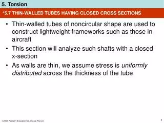
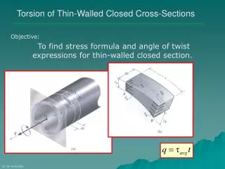
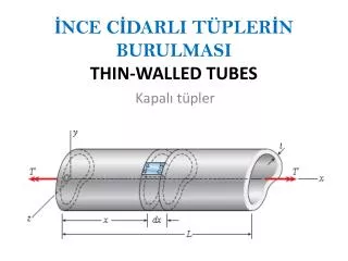
*5.7 THIN-WALLED TUBES HAVING CLOSED CROSS SECTIONS. Thin-walled tubes of noncircular shape are used to construct lightweight frameworks such as those in aircraft This section will analyze such shafts with a closed x-section

E N D
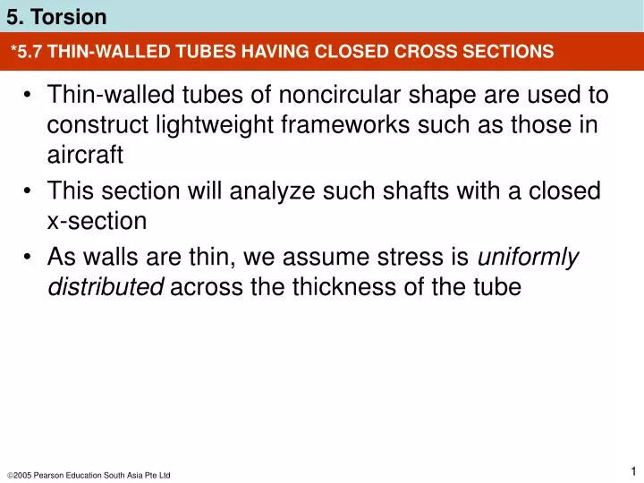
*5.7 THIN-WALLED TUBES HAVING CLOSED CROSS SECTIONS • Thin-walled tubes of noncircular shape are used to construct lightweight frameworks such as those in aircraft • This section will analyze such shafts with a closed x-section • As walls are thin, we assume stress is uniformly distributed across the thickness of the tube
q = avgt *5.7 THIN-WALLED TUBES HAVING CLOSED CROSS SECTIONS Shear flow • Force equilibrium requires the forces shown to be of equal magnitude but opposite direction, thus AtA = BtB • This product is called shear flow q, and can be expressed as Shear flow measures force per unit length along tube’s x-sectional area
T 2tAm avg = *5.7 THIN-WALLED TUBES HAVING CLOSED CROSS SECTIONS Average shear stress avg = average shear stress acting over thickness of tube T = resultant internal torque at x-section t = thickness of tube where avg is to be determined Am = mean area enclosed within boundary of centerline of tube’s thickness
T 2Am q = TL 4Am2G ds t = ∫ O *5.7 THIN-WALLED TUBES HAVING CLOSED CROSS SECTIONS Average shear stress Since q = avgt, the shear flow throughout the x-section is Angle of twist Can be determined using energy methods
*5.7 THIN-WALLED TUBES HAVING CLOSED CROSS SECTIONS IMPORTANT • Shear flow q is a product of tube’s thickness and average shear stress. This value is constant at all points along tube’s x-section. Thus, largestaverage shear stress occurs where tube’s thickness is smallest • Both shear flow and average shear stress act tangent to wall of tube at all points in a direction to contribute to resultant torque
EXAMPLE 5.16 Square aluminum tube as shown. Determine average shear stress in the tube at point A if it is subjected to a torque of 85 N·m. Also, compute angle of twist due to this loading. Take Gal = 26 GPa.
T 2tAm avg = = ... = 1.7 N/mm2 EXAMPLE 5.16 (SOLN) Average shear stress Am = (50 mm)(50 mm) = 2500 mm2 Since t is constant except at corners, average shear stress is same at all points on x-section. Note that avg acts upward on darker-shaded face, since it contributes to internal resultant torque T at the section
TL 4Am2G ds t = ∫ O = ... = 0.196(10-4) mm-1∫ds O EXAMPLE 5.16 (SOLN) Angle of twist Here, integral represents length around centerline boundary of tube, thus = 0.196(10-4) mm-1[4(50 mm)] = 3.92 (10-3) rad
5.8 STRESS CONCENTRATION • Three common discontinuities of the x-section are: • is a coupling, for connecting 2 collinear shafts together • is a keyway used to connect gears or pulleys to a shaft • is a shoulder fillet used to fabricate a single collinear shaft from 2 shafts with different diameters
5.8 STRESS CONCENTRATION • Dots on x-section indicate where maximum shear stress will occur • This maximum shear stress can be determined from torsional stress-concentration factor, K
max = K(Tc/J) 5.8 STRESS CONCENTRATION • K, can be obtained from a graph as shown • Find geometric ratio D/d for appropriate curve • Once abscissa r/d calculated, value of K found along ordinate • Maximum shear stress is then determined from
5.8 STRESS CONCENTRATION IMPORTANT • Stress concentrations in shafts occur at points of sudden x-sectional change. The more severe the change, the larger the stress concentration • For design/analysis, not necessary to know exact shear-stress distribution on x-section. Instead, obtain maximum shear stress using stress concentration factor K • If material is brittle, or subjected to fatigue loadings, then stress concentrations need to be considered in design/analysis.
EXAMPLE 5.18 Stepped shaft shown is supported at bearings at A and B. Determine maximum stress in the shaft due to applied torques. Fillet at junction of each shaft has radius r = 6 mm.
EXAMPLE 5.18 (SOLN) Internal torque By inspection, moment equilibrium about axis of shaft is satisfied. Since maximum shear stress occurs at rooted ends of smaller diameter shafts, internal torque (30 N·m) can be found by applying method of sections
2(40 mm) 2(20 mm) D d = = 2 6 mm) 2(20 mm) r d = = 0.15 EXAMPLE 5.18 (SOLN) Maximum shear stress From shaft geometry, we have Thus, from the graph, K = 1.3 max = K(Tc/J) = ... = 3.10 MPa
EXAMPLE 5.18 (SOLN) Maximum shear stress From experimental evidence, actual stress distribution along radial line of x-section at critical section looks similar to:
*5.9 INELASTIC TORSION • To perform a “plastic analysis” for a material that has yielded, the following conditions must be met: • Shear strains in material must vary linearly from zero at center of shaft to its maximum at outer boundary (geometry) • Resultant torque at section must be equivalent to torque caused by entire shear-stress distribution over the x-section (loading)
T = 2∫A 2 d *5.9 INELASTIC TORSION • Expressing the loading condition mathematically, we get: Equation 5-23
TY = (/2) Yc3 d = (dx/) *5.9 INELASTIC TORSION A. Maximum elastic torque • For maximum elastic shear strainY, at outer boundary of the shaft, shear-strain distribution along radial line will look like diagram (b) • Based on Eqn 5-23, From Eqn 5-13,
T = (Y /6) (4c3 Y3) *5.9 INELASTIC TORSION B. Elastic-plastic torque • Used when material starts yielding, and the yield boundary moves inward toward the shaft’s centre, producing an elasticcore. • Also, outer portion of shaft forms a plastic annulus or ring • General formula for elastic-plastic material behavior,
TP = (2/3)Y c3 TP = 4TY / 3 *5.9 INELASTIC TORSION B. Elastic-plastic torque Plastic torque • Further increases in T will shrink the radius of elastic core till all the material has yielded • Thus, largest possible plastic torque is Comparing with maximum elastic torque, Angle of twist cannot be uniquely defined.
*5.9 INELASTIC TORSION C. Ultimate torque • Magnitude of Tu can be determined “graphically” by integrating Eqn 5-23
*5.9 INELASTIC TORSION C. Ultimate torque • Segment shaft into finite number of rings • Area of ring is multiplied by shear stress to obtain force • Determine torque with the product of the force and • Addition of all torques for entire x-section results in the ultimate torque, Tu≈ 2 2
*5.9 INELASTIC TORSION IMPORTANT • Shear-strain distribution over radial line on shaft based on geometric considerations and is always remain linear • Shear-stress distribution must be determined from material behavior or shear stress-strain diagram • Once shear-stress distribution established, the torque about the axis is equivalent to resultant torque acting on x-section • Perfectly plastic behavior assumes shear-stress distribution is constant and the torque is called plastic torque
EXAMPLE 5.19 Tubular shaft made of aluminum alloy with elastic -diagram as shown. Determine (a) maximum torque that can be applied without causing material to yield, (b) maximum torque or plastic torque that can be applied to the shaft. What should the minimum shear strain at outer radius be in order to develop a plastic torque?
EXAMPLE 5.19 (SOLN) Maximum elastic torque Shear stress at outer fiber to be 20 MPa. Using torsion formula Y = (TY c/J); TY = 3.42 kN·m Values at tube’s inner wall are obtained by proportion.
EXAMPLE 5.19 (SOLN) Plastic torque Shear-stress distribution shown below. Applying = Y into Eqn 5-23: TP = ... = 4.10 kN·m For this tube, TP represents a 20% increase in torque capacity compared to elastic torque TY.
EXAMPLE 5.19 (SOLN) Outer radius shear strain Tube becomes fully plastic when shear strain at inner wall becomes 0.286(10-3) rad. Since shear strain remains linear over x-section, plastic strain at outer fibers determined by proportion: o = ... = 0.477(10-3) rad
*5.10 RESIDUAL STRESS • Residual stress distribution is calculated using principles of superposition and elastic recovery
EXAMPLE 5.21 Tube made from brass alloy with length of 1.5 m and x-sectional area shown. Material has elastic-plastic -diagram shown.G = 42 GPa. Determine plastic torque TP. What are the residual-shear-stress distribution and permanent twist of the tube that remain if TP is removed just after tube becomes fully plastic?
EXAMPLE 5.21 (SOLN) Plastic torque Applying Eqn 5-23, TP = ... = 19.24(106) N·mm When tube is fully plastic, yielding started at inner radius, ci = 25 mm and Y = 0.002 rad, thus angle of twist for entire tube is P = Y (L/ci) = ... = 0.120 rad
EXAMPLE 5.21 (SOLN) Plastic torque Then TP is removed, then “fictitious” linear shear-stress distribution in figure (c) must be superimposed on figure (b). Thus, maximum shear stress or modulus of rupture computed from torsion formula, r = (TPco)/J = ... = 104.52 MPa i = (104.52 MPa)(25 mm/50 mm) = 52.26 MPa
EXAMPLE 5.21 (SOLN) Plastic torque Angle of twist ’P upon removal of TP is ’P= (TP L)/(JG) = ... = 0.0747 rad Residual-shear-stress distribution is shown. Permanent rotation of tube after TP is removed, + = 0.120 0.0747 = 0.0453 rad
CHAPTER REVIEW • Torque causes a shaft with circular x-section to twist, such that shear strain in shaft is proportional to its radial distance from its centre • Provided that material is homogeneous and Hooke’s law applies, shear stress determined from torsion formula, = (Tc)/J • Design of shaft requires finding the geometric parameter, (J/C) = (T/allow) • Power generated by rotating shaft is reported, from which torque is derived; P = T
T(x) dx JG L ∫0 = TL JG = CHAPTER REVIEW • Angle of twist of circular shaft determined from • If torque and JG are constant, then • For application, use a sign convention for internal torque and be sure material does not yield, but remains linear elastic
CHAPTER REVIEW • If shaft is statically indeterminate, reactive torques determined from equilibrium, compatibility of twist, and torque-twist relationships, such as = TL/JG • Solid noncircular shafts tend to warp out of plane when subjected to torque. Formulas are available to determine elastic shear stress and twist for these cases • Shear stress in tubes determined by considering shear flow. Assumes that shear stress across each thickness of tube is constant
CHAPTER REVIEW • Shear stress in tubes determined from = T/2tAm • Stress concentrations occur in shafts when x-section suddenly changes. Maximum shear stress determined using stress concentration factor, K (found by experiment and represented in graphical form). max = K(Tc/J) • If applied torque causes material to exceed elastic limit, then stress distribution is not proportional to radial distance from centerline of shaft
CHAPTER REVIEW • Instead, such applied torque is related to stress distribution using the shear-stress-shear-strain diagram and equilibrium • If a shaft is subjected to plastic torque, and then released, it will cause material to respond elastically, causing residual shear stress to be developed in the shaft