Download
1 / 44
440 likes | 523 Vues
ILC Cryogenic Systems Reference Design . T. Peterson M. Geynisman, A. Klebaner, V. Parma, L. Tavian, J. Theilacker 20 July 2007. Reference Design.

E N D
ILC Cryogenic Systems Reference Design T. Peterson M. Geynisman, A. Klebaner, V. Parma, L. Tavian, J. Theilacker 20 July 2007
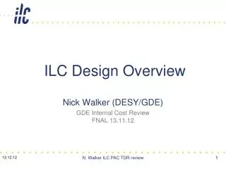
Reference Design • A “Global Design Effort” (GDE) began in 2005 to study a TeV scale electron-positron linear accelerator based on superconducting radio-frequency (RF) technology, called the International Linear Collider (ILC). • In early 2007, the design effort culminated in a “Reference Design” for the ILC, closely based on the earlier TESLA design. • This presentation and associated paper present some of the main features of the reference design for the cryogenic system. CEC 2007
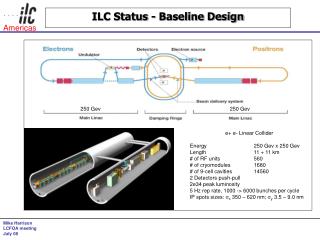
International Linear Collider CEC 2007
International Linear Collider • Each linac is about 14 km long • Damping rings about 6.7 km circumference CEC 2007
9 cell niobium RF cavity • 9-cell niobium RF cavities are welded into titanium helium vessels • Eight (or nine) of these “dressed” cavities are assembled into a cryostat called a “cryomodule” CEC 2007
Main linac cryomodule CEC 2007
Cryomodule from TESLA TDR CEC 2007
Cryomodule on test stand at DESY CEC 2007
ILC RF cryomodule count • Above are installed numbers, not counting uninstalled spares CEC 2007
ILC superconducting magnets • About 640 1.3 GHz modules have SC magnets • Other SC magnets are outside of RF modules • 290 meters of SC helical undulators, in 2 - 4 meter length units, in the electron side of the main linac as part of the positron source • In damping rings -- 8 strings of wigglers (4 strings per ring), 10 wigglers per string x 2.5 m per wiggler • Special SC magnets in sources, RTML, and beam delivery system CEC 2007
A cryogenic “string” CEC 2007
Main Linac Layout - 1 CEC 2007
Main Linac Layout - 2 CEC 2007
Cryogenic plant arrangement CEC 2007
Major cryogenic distribution components • 6 large (2 K system) tunnel service or “distribution” boxes • Connect refrigerators to tunnel components and allow for sharing load between paired refrigerators • 20 large (2 K) tunnel cryogenic unit “feed” boxes • Terminate and/or cross-connect the 10 cryogenic units • ~132 large (2 K) string “connecting” or string “end” boxes of several types • Contain valves, heaters, liquid collection vessels, instrumentation, vacuum breaks • Note that these have many features of modules! • ~3 km of large transfer lines (including 2 Kelvin lines) • ~100 “U-tubes” (removable transfer lines) • Damping rings are two 4.5 K systems • Various distribution boxes and ~7 km of small transfer lines • BDS and sources include transfer lines to isolated components • Various special end boxes for isolated SC devices CEC 2007
Cryogenic unit length limitations • 25 KW total equivalent 4.5 K capacity • Heat exchanger sizes • Over-the-road sizes • Experience • Cryomodule piping pressure drops with 2+ km distances • Cold compressor capacities • With 192 modules, we reach our plant size limits, cold compressor limits, and pressure drop limits • 192 modules results in 2.47 km long cryogenic unit • 5 units (not all same length) per 250 GeV linac • Divides linac nicely for undulators at 150 GeV CEC 2007
Beam line vacuum system 2288 m 571 m Special cold gate valve High speed safety shutter 150 l/s Ion pump All metal Gate valve LD LD RGA RGA John Noonan, ANL Yusuke Suetsugu,KEK Paolo Michelato, INFN Milano 2 TMP pumping units with high sensitivity LD and RGA, safety, clean venting system, slow start pumping etc. CEC 2007
Insulating vacuum system 571 m ( 4 strings) Connections for screw pump 142 m By pass Vacuum Breaks LD LD John Noonan, ANL Yusuke Suetsugu,KEK Paolo Michelato, INFN Milano 4 TMP pumping units: 2 with LD (leak detector) + 2 large screw pump for fore pumping CEC 2007
Heat loads scaled from TESLA TDR CEC 2007
Module predicted heat loads -- 2K TESLA ILC 9-8-9 CEC 2007
Module predicted heat loads -- 5K TESLA ILC 9-8-9 CEC 2007
Module predicted heat loads -- 40K TESLA ILC 9-8-9 CEC 2007
Cryogenic unit parameters CEC 2007
CERN LHC capacity multipliers • We have adopted a modified version of the LHC cryogenic capacity formulation for ILC • Cryo capacity = Fo x (Qd x Fud + Qs x Fus) • Fo is overcapacity for control and off-design or off-optimum operation • Qs is predicted static heat load • Fus is uncertainty factor static heat load estimate • Fud is uncertainty factor dynamic heat load estimate • Qd is predicted dynamic heat load CEC 2007
300 mm 2 K vapor tube (B) • Goal is no more than 3.0 mbar delta-P • 300 mm ID tube pressure drop is 2.25 mbar (at 30 mbar) • 2.5 km • Assumed worst case flow, maximum plant output including all factors (0.93 gr/sec per module) • Pressure drop at about the limit. With much higher heat loads we would want shorter cryogenic units. • (my calculations, also in agreement with others) CEC 2007
Type 4 cryomodule pipe sizes CEC 2007
Pipe size summary now (July 07) CEC 2007
Helium Volume in a Cryomodule CEC 2007
Helium Inventory in a Cryomodule CEC 2007
Off-design operation • Helium venting with loss of vacuum • Cryostat insulating vacuum (~6 W/cm^2) • Cavity vacuum (~2-4 W/cm^2) • Large flow rates • 300 mm header acts as buffer • No venting to tunnel • Warm-up and cool-down • Relatively low mass compared to magnet systems • Allow for greater mass of magnet package CEC 2007
Maximum allowable pressures • Helium vessel, 2 phase pipe, 300 mm header • 2 bar warm • Limited by cavity detuning • Issue for pushing warm-up and cool-down flows • 4 bar cold • Limited by cavity detuning • Issue for emergency venting • Shield pipes • 20 bar • Need high pressure for density to reduce flow velocities and pressure drops CEC 2007
Main linac dominates ILC cryogenics but there is more . . . • The main linac cryoplants and associated equipment make up about 60% of total ILC cryogenic system costs • Main linac distribution is another 20% of total ILC cryogenic system costs • About half of that is 132 string connecting boxes • Total is about 80% of ILC cryogenic system costs attributable to the main linac CEC 2007
Source cryogenics • Electron source • 25 modules, assembled as two strings • SC spin rotator section, 50 m long • Positron source • 22 modules, about half special with extra magnets, assembled as two strings • Undulator cryo in Main Linac • Overall module heat taken as same load as electron side • Costed as separate cryoplants, but may at least share compressors with pts 2 and 3. CEC 2007
shaft/large cavern A Arc 2 (818 m) short straight B (249 m) short straight A (249 m) wiggler wiggler e+ RF cavities Arc 1 (818 m) Arc 3 (818 m) long straight 1 (400 m) long straight 2 (400 m) injection extraction small cavern 1 small cavern 2 Arc 4 (818 m) Arc 6 (818 m) RF cavities wiggler wiggler short straight D (249 m) short straight C (249 m) Arc 5 (818 m) shaft/large cavern C A. Wolski, 9 Nov 2006 CEC 2007
Damping ring cryogenics • Result is two cryoplants each of total capacity equivalent to 3.5 kW at 4.5 K. CEC 2007
Beam delivery system cryogenics • Crab cavities (3.9 GHz) at 1.8 K plus magnets • Not including detector cooling nor moveable magnets • 80 W at 1.8 K ==> 4 gr/sec liquefaction plus room-temperature pumping • In total for one 14 mr IR • 4 gr/sec at 4.5 K • 400 W at 4.5 K • 2000 W at 80 K • Overall capacity equivalent to about 1.9 kW at 4.5 K for one plant cooling both sides of one IR • Similar in size and features to an RF test facility refrigerator CEC 2007
ILC cryogenic system inventory Since we have not counted all the cryogenic subsystems and storage yet, ILC probably ends up with a bit more inventory than LHC CEC 2007
ILC cryogenic plant size summary • TESLA 500 TDR for comparison • 5 plants at ~5.15 MW installed • 2 plants at ~3.5 MW installed • Total 32.8 MW installed • Plus some additional for damping rings CEC 2007
Cryoplants compared to TESLA • Why more cryo power in ILC than TESLA? • Dynamic load up with gradient squared (linac length reduced by gradient) • Lower assumptions about plant efficiency, in accordance with recent industrial estimate, see table below CEC 2007
Cryogenic system design status • Fairly complete accounting of cold devices with heat load estimates and locations • Focus has been on main linac cryomodules • Some other cold devices still not well defined • Some heat loads are very rough estimates • Cryogenic plant capacities have been estimated • Overall margin about 1.54 • Main linac plants dominate, each at 20 kW @ 4.5 K equivalent total capacity • Component conceptual designs (distribution boxes, end boxes, transfer lines) are still sketchy • Need these to define space requirements and make cost estimates • Used area system lattice designs to develop transfer line lengths and conceptual cryosystem layouts CEC 2007
ILC Engineering Design Phase • A 2 - 3 year effort to create a more complete ILC design • Starting now • Precise scope not yet defined • Work will be internationally distributed • ILC cryogenic system and cryomodule design are a major part of the engineering design phase effort CEC 2007
Towards the EDR • Contract with industry for main linac cryogenic plant conceptual designs and cost studies • Need to integrate plant cycle with cryomodule conditions • Will feed back to system design and cryomodule design • Continue to refine heat load estimates and required plant sizes • Refine system layout schemes to optimize plant locations and transfer line distances • Particularly for the sources, damping rings, and beam delivery system • Develop cryogenic process, flow, and instrumentation diagrams and conceptual equipment layouts • Develop more detailed conceptual designs for the various end boxes, distribution boxes, and transfer lines • Refine liquid control schemes so as to understand use of heaters and consequent heat loads (allowed for in Fo = 1.4) CEC 2007
Towards the EDR - 2 • Consider impact of cool-down, warm-up and off-design operations • Evaluate requirements for loss-of-vacuum venting • Conceptual designs for large 2 kelvin heat exchangers • Not distributed as in LHC • Consider how to group surface components to reduce surface impact • Compliance with engineering standards, particularly in cryogenic modules • Damping ring cryogenic system • Beam delivery cryogenic system CEC 2007
For more information • http://www.linearcollider.org/ • The ILC home page • Includes a link to the full Reference Design Report (RDR) • http://tesla-new.desy.de/ • TESLA Technology Collaboration home page • Links to RF cavity database, publications and ~15 years of 1.3 GHz SRF documentation and experience, the basis for ILC technology • E-mail me at Tommy@fnal.gov CEC 2007