Download
1 / 57
570 likes | 669 Vues
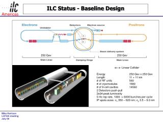
ILC Cryogenic Systems Reference Design. T. Peterson M. Geynisman, A. Klebaner, V. Parma, L. Tavian, J. Theilacker 20 July 2007. Reference Design.

E N D
ILC Cryogenic Systems Reference Design T. Peterson M. Geynisman, A. Klebaner, V. Parma, L. Tavian, J. Theilacker 20 July 2007 CEC 2007
Reference Design • A Global Design Effort (GDE) began in 2005 to study a TeV scale electron-positron linear accelerator based on superconducting radio-frequency (RF) technology, called the International Linear Collider (ILC). • In early 2007, the design effort culminated in a “reference design” for the ILC, closely based on the earlier TESLA design. • This presentation and associated paper present some of the main features of the reference design for the cryogenic system CEC 2007
ILC cryogenic system definition • The cryogenic system is taken to include cryogen distribution as well as production • Cryogenic plants and compressors • Including evaporative cooling towers • Distribution and interface boxes • Including non-magnetic, non-RF cold tunnel components • Transfer lines • Cryo instrumentation and cryo plant controls • Cryogenic system design is closely integrated with cryogenic SRF module and magnet design • R&D systems and production test systems will also include significant cryogenics CEC 2007
ILC RF cryomodule count • Above are installed numbers, not counting uninstalled spares CEC 2007
ILC superconducting magnets • About 640 1.3 GHz modules have SC magnets • Other SC magnets are outside of RF modules • 290 meters of SC helical undulators, in 2 - 4 meter length units, in the electron side of the main linac as part of the positron source • In damping rings -- 8 strings of wigglers (4 strings per ring), 10 wigglers per string x 2.5 m per wiggler • Special SC magnets in sources, RTML, and beam delivery system CEC 2007
Major cryogenic distribution components • 6 large (2 K system) tunnel service or “distribution” boxes • Connect refrigerators to tunnel components and allow for sharing load between paired refrigerators • 20 large (2 K) tunnel cryogenic unit “feed” boxes • Terminate and/or cross-connect the 10 cryogenic units • ~132 large (2 K) string “connecting” or string “end” boxes of several types • Contain valves, heaters, liquid collection vessels, instrumentation, vacuum breaks • Note that these have many features of modules! • ~3 km of large transfer lines (including 2 Kelvin lines) • ~100 “U-tubes” (removable transfer lines) • Damping rings are two 4.5 K systems • Various distribution boxes and ~7 km of small transfer lines • BDS and sources include transfer lines to isolated components • Various special end boxes for isolated SC devices CEC 2007
XFEL linac cryogenic components This slide from XFEL_Cryoplant_120506.ppt by Bernd Petersen ‚regular‘ string connection box End-BOX The ILC string end box concept is like this -- a short, separate cryostat Cool-down/warm-up JT The ILC cryogenic unit service boxes may be offset from the beamline, reducing drift space length, with a concept like this. Feed-Box Bunch Compressor Bypass Transferline (only 1-phase helium) CEC 2007
XFEL Bunch-Compressor-Transferlines This slide from XFEL_Cryoplant_120506.ppt by Bernd Petersen The cryogenic unit service boxes may be offset from the beamline as shown, but they would be larger. Drift space is reduced to about 2 meters on each end plus warm drift space. CEC 2007
TTF cold-warm transition ~ 2 m Cryogenic lines End module Structure for vacuum load Warm beam pipe CEC 2007
Magnet current leads • Conductively cooled (no vapor flow) • Insulated bronze inside a stainless sleeve • Based on the LHC corrector leads (LHC Project Report 691) Kay Jensch CEC 2007
Main Linac • The main linac cryoplants and associated equipment make up about 60% of total ILC cryogenic system costs • Main linac distribution is another 20% of total ILC cryogenic system costs • About half of that is 132 string connecting boxes • Total is about 80% of ILC cryogenic system costs attributable to the main linac • The following slides describe some of the main linac cryosystem concepts • Will focus on main linac, then follow with about 1 slide each for the other areas CEC 2007
Main Linac Layout CEC 2007
Main Linac Layout - 2 CEC 2007
Cryogenic unit length limitations • 25 KW total equivalent 4.5 K capacity • Heat exchanger sizes • Over-the-road sizes • Experience • Cryomodule piping pressure drops with 2+ km distances • Cold compressor capacities • With 192 modules, we reach our plant size limits, cold compressor limits, and pressure drop limits • 192 modules results in 2.47 km long cryogenic unit • 5 units (not all same length) per 250 GeV linac • Divides linac nicely for undulators at 150 GeV CEC 2007
Cryogenic plant arrangement CEC 2007
Beam line vacuum system 1/2 571 m (4 strings) 142 m Ion getter pump LD LD RGA RGA John Noonan, ANL Yusuke Suetsugu,KEK Paolo Michelato, INFN Milano 2 TMP pumping units with high sensitivity LD and RGA, safety, clean venting system, slow start pumping etc. CEC 2007
Beam line vacuum system 2/2 2288 m 571 m Special cold gate valve High speed safety shutter 150 l/s Ion pump All metal Gate valve LD LD RGA RGA John Noonan, ANL Yusuke Suetsugu,KEK Paolo Michelato, INFN Milano 2 TMP pumping units with high sensitivity LD and RGA, safety, clean venting system, slow start pumping etc. CEC 2007
Insulating vacuum system 571 m ( 4 strings) Connections for screw pump 142 m By pass Vacuum Breaks LD LD John Noonan, ANL Yusuke Suetsugu,KEK Paolo Michelato, INFN Milano 4 TMP pumping units: 2 with LD (leak detector) + 2 large screw pump for fore pumping CEC 2007
Coupler vacuum system 35 m (!) 75 l/s Ion pump TSP 24 All metal CF40 90 ° valve LD RGA John Noonan, ANL Yusuke Suetsugu,KEK Paolo Michelato, INFN Milano CEC 2007
Heat loads scaled from TESLA TDR CEC 2007
Module predicted heat loads -- 2K TESLA ILC 9-8-9 CEC 2007
Module predicted heat loads -- 5K TESLA ILC 9-8-9 CEC 2007
Module predicted heat loads -- 40K TESLA ILC 9-8-9 CEC 2007
Power required for a non-isothermal load • Use • Where P is the ideal room-temperature power required to remove a non-isothermal heat load • I will show the use of this later in calculating the ILC cryogenic system power CEC 2007
Cryogenic unit parameters CEC 2007
CERN LHC capacity multipliers • We have adopted a modified version of the LHC cryogenic capacity formulation for ILC • Cryo capacity = Fo x (Qd x Fud + Qs x Fus) • Fo is overcapacity for control and off-design or off-optimum operation • Qs is predicted static heat load • Fus is uncertainty factor static heat load estimate • Fud is uncertainty factor dynamic heat load estimate • Qd is predicted dynamic heat load CEC 2007
Heat Load evolution in LHC Basic Configuration: Pink Book 1996 Design Report: Design Report Document 2004 At the early design phase of a project, margins are needed to cover unknown data or project configuration change. CEC 2007
Cryomodule sketch from TDR CEC 2007
Pressure drop design goals -- 1 • 2 K supply (line A) -- delta-P = 0.1 bar max • Supply to JT valve so pressure drop not a major issue. Dropping pressure through valve anyway. • Consider 4.5 K filling • Allow 0.1 bar max for liquid supply during fill • Assume flow same as with full 2 K load • “300 mm” tube (line B) -- dP = 3 mbar max • Tube size is essentially fixed, taken as a parameter restricting cryo unit length • Taking 3 mbar ==> 33 mK (2.000 K to 2.033 K range over cryogenic unit) CEC 2007
Pressure drop design goals -- 2 • 5 K - 8 K thermal shield (lines C, D) -- 0.2 bar dP • Operating between 5 bar and 4.0 - 4.5 bar • Pressure and pressure range are somewhat arbitrary choices right now! • Must be integrated with plant cycle (true for all flow loops) • Need >50% of dP in valve for control • So aim for 0.2 bar delta-P or less • 40 K - 80 K thermal shield (lines E, F) -- 1.0 bar dP • Operating between 16 bar and 14 bar • Again, must be integrated with plant cycle (true for all flow loops) • This is conservatively low pressure and large delta-P • Want >50% of delta-P in valve for control • So aim for 1 bar delta-P or less CEC 2007
300 mm 2 K vapor tube (B) • Goal is no more than 3.0 mbar delta-P • 300 mm ID tube pressure drop is 2.25 mbar (at 30 mbar) • 2.5 km • Assumed worst case flow, maximum plant output including all factors (0.93 gr/sec per module) • Pressure drop at about the limit. With much higher heat loads we would want shorter cryogenic units. • (my calculations, also in agreement with others) CEC 2007
Type 4 cryomodule pipe sizes CEC 2007
Pipe size summary now (July 07) CEC 2007
Helium Volume in a Cryomodule CEC 2007
Helium Inventory in a Cryomodule CEC 2007
Off-design operation • Helium venting with loss of vacuum • Cryostat insulating vacuum (~6 W/cm^2) • Cavity vacuum (~2-4 W/cm^2) • Large flow rates • 300 mm header acts as buffer • No venting to tunnel • Warm-up and cool-down • Relatively low mass compared to magnet systems • Allow for greater mass of magnet package CEC 2007
Maximum allowable pressures • Helium vessel, 2 phase pipe, 300 mm header • 2 bar warm • Limited by cavity detuning • Issue for pushing warm-up and cool-down flows • 4 bar cold • Limited by cavity detuning • Issue for emergency venting • Shield pipes • 20 bar • Need high pressure for density to reduce flow velocities and pressure drops CEC 2007
Source cryogenics • Electron source • 25 modules, assembled as two strings • SC spin rotator section, 50 m long • Positron source • 22 modules, about half special with extra magnets, assembled as two strings • Undulator cryo in Main Linac • Overall module heat taken as same load as electron side • Costed as separate cryoplants, but may at least share compressors with pts 2 and 3. CEC 2007
RTML • Included in Main Linac layout as a cryogenic unit cooled from pts 6 and 7 • Cost of refrigeration scaled like 2 K heat loads CEC 2007
RTML BC2 follows main linac pattern CEC 2007
Damping ring cryogenics • Result is two cryoplants each of total capacity equivalent to 3.5 kW at 4.5 K. CEC 2007
shaft/large cavern A Arc 2 (818 m) short straight B (249 m) short straight A (249 m) wiggler wiggler e+ RF cavities Arc 1 (818 m) Arc 3 (818 m) long straight 1 (400 m) long straight 2 (400 m) injection extraction small cavern 1 small cavern 2 Arc 4 (818 m) Arc 6 (818 m) RF cavities wiggler wiggler short straight D (249 m) short straight C (249 m) Arc 5 (818 m) shaft/large cavern C A. Wolski, 9 Nov 2006 CEC 2007
Beam delivery system cryogenics • Crab cavities (3.9 GHz) at 1.8 K plus magnets • Not including detector cooling nor moveable magnets • 80 W at 1.8 K ==> 4 gr/sec liquefaction plus room-temperature pumping • In total for one 14 mr IR • 4 gr/sec at 4.5 K • 400 W at 4.5 K • 2000 W at 80 K • Overall capacity equivalent to about 1.9 kW at 4.5 K for one plant cooling both sides of one IR • Similar in size and features to an RF test facility refrigerator CEC 2007
ILC cryogenic system inventory Since we have not counted all the cryogenic subsystems and storage yet, ILC probably ends up with a bit more inventory than LHC CEC 2007
ILC cryogenic plant size summary • TESLA 500 TDR for comparison • 5 plants at ~5.15 MW installed • 2 plants at ~3.5 MW installed • Total 32.8 MW installed • Plus some additional for damping rings CEC 2007
Cryoplants compared to TESLA • Why more cryo power in ILC than TESLA? • Dynamic load up with gradient squared (linac length reduced by gradient) • Lower assumptions about plant efficiency, in accordance with recent industrial estimate, see table below CEC 2007
Items associated with plants • Compressor systems (electric motors, starters, controls, screw compressors, helium purification, piping, oil cooling and helium after-cooling) • Upper cold box (vacuum-jacketed heat exchangers, expanders, 80 K purification) • Lower cold box (vacuum-jacketed heat exchangers, expanders, cold compressors) • Gas storage (large tank “farms”, piping, valves) • Liquid storage (a lot, amount to be determined) CEC 2007
Architecture: Main Linac P3 CEC 2007
Architecture: Main Linac P4 CEC 2007