Download
1 / 19
190 likes | 381 Vues
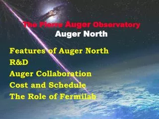
Roger Kieckhafer (rmkieckh@mtu.edu) for the Pierre Auger Collaboration. Hard Real-Time Wireless Communication in the Northern Pierre Auger Observatory. Auger North and South. From the beginning: two sites were planned Northern and Southern Hemispheres Auger North: Planning Stages

E N D
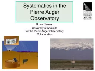
Roger Kieckhafer (rmkieckh@mtu.edu) for the Pierre Auger Collaboration Hard Real-Time Wireless Communication in theNorthern Pierre Auger Observatory RT2010 - Lisboa
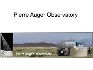
Auger North and South • From the beginning: two sites were planned • Northern and Southern Hemispheres • Auger North: • Planning Stages • Lamar, Colorado USA • Auger South: • Fully Operational • Malargue, Argentina RT2010 - Lisboa
Flourescence Detector (FD)Telescopes Surface Detector (SD) Array ObservatoryFunctionalOverview H+ Shower of secondary particles Timestamps+ other data RT2010 - Lisboa
T2 Trigger Message(Timestamps of promising events) T3 Trigger Message(Req. data on correlated timestamps) T3 Response Message Stream(Return data on req. timestamps) SD Wireless – Real-Time Sequence SD Station(in the field) CDAS(ObservatoryCampus) Record andfiltertimestamps CorrelateTimestampsAcross Stations Access Dataon requestedtimestamps Conductfurther analysis RT2010 - Lisboa
Auger North vs South. • Auger North puts greater demands on the wireless net • Auger North will be much larger • Auger North will have higher data rates • Auger North will have roughly the same real-time deadlines RT2010 - Lisboa
AugerSouthFootprint AugerNorthFootprint Auger North Site RT2010 - Lisboa
Auger South SD Communication • Wide area wireless net • Microwave towers form a communication backbone • 4 Collector Towers on periphery of array • 1 Destination Tower at Malargue campus • 1-hop station-to-tower link for each station • Remarkably flat topography in the interior • Sizable hills on the periphery of the array • Easy to give each station a clear line-of-sight to a tower RT2010 - Lisboa
Auger North Communication Problem • Array is 7 x Bigger than South • Need > 30 towers @ 45 mto stay within radio range • Terrain is Rougher than South • No convenient peripheral hills • Many small internal hills & ridges • Can not get reliable line-of-sight over that terrain • Bottom line: • 1-hop Station-to-Tower comm.does not work • >10% of stations incommunicado Lamar Springfield RT2010 - Lisboa
Only Viable Option: Peer-to-Peer WSN • Auger North uses a new paradigm called “WAHREN” • WAWireless Architecture • Infrastructure Nodes (INs) = the dominant feature • Non-Infrastructure Nodes (NINs) = optional “guest” nodes • HRHard Real-time • Time-Bounded subject to hard real-time deadlines • Deterministic not subject to stochastic-timing • ENEmbedded Networks • Fault-Tolerant Fully Redundant Comp. & Comm. • Fully Distributed No leaders, coordinators, masters RT2010 - Lisboa
1 2 3 4 5 6 7 8 9 10 2 4 6 8 10 1 3 5 7 9 WAHREN Interconnection Topology • Uses 2nd Order Power chains (“Braided Chain”) • Graph Topology: • Start with a basic chain – nearest neighbor comm only • Extend range to reach second-nearest neighbors • Useful Physical Realization = 2D Triangular Mesh q RT2010 - Lisboa
10’ 9’ 8’ Must be Preventedby Protocol 7’ Mobius Fold 2 4 6 8 10 1 3 5 7 9 Turning Corners • Our Target Infrastructures are not always straight lines • Gentle curves are no problem • But what aboutsharp corners? • Existence of Mobiusfold is transparentto the topology RT2010 - Lisboa
TDMA CSMA NIN Trans IN Transmissions Hybrid TDMA/CSMA MAC Protocol • Hybrid Window Combines TDMA & CSMA slots • Enough TDMA slots for all INs within interference range • Enough CSMA slots for expected/desired number of NINs • Auger North-Specific Comm Window • 8 TDMA slots – for neighboring Infrastructure Nodes • Based on predicted interference range, and • Alternating use of 2 RF channels • 1 CSMA slot – expecting few non-infrastructure nodes Window RT2010 - Lisboa
1 3 5 Win-3 Win-1 Win-5 Win-0 Win-2 Win-4 2 4 6 Systolic Broadcast Scheduling Protocol • Unidirectional Single-Source Broadcast: • Window 0: Node 0 originates a message • Window w: Node w forwards node 0’s message • Redundancy: Node Red = Path Red = Time Red = 2 • Unidirectional Multi-Source Broadcast • Window 0: All nodes originate a message • Window w: Node k forwards node (k-w)’s message 0 RT2010 - Lisboa
Sector Service Area Adapting WAHREN to Auger Topology • Array is partitioned into “service areas” • Each served by one Concentrator Station • Each Service Area is partitioned into “sectors” • Sectors can be triangular, rectangular, or quite amorphous RT2010 - Lisboa
Comm Sequence in One Sector • Auger North SD is a 2 mi square array tilted 45 degrees • Any adjacent pair of E-W rows or N-S columns naturally forms a 2nd order power chain • Can easily be organized into Backbones & Side Chains • Linked at Mobius Folds Side Chains Concentrator Station Fiber to Campus PCHost Backbone RT2010 - Lisboa
System Throughput • Can Meet all required deadlines: • With up-to 128 stations / sector • 4,400 stations 35 sectors • 8 sectors/concent. 5 concents. • IF they are all centrally located. • Current Proposal is to put concentrators at the 5 FDs • Power, fiber & bldgs already exist • But, some FDs are on Periphery • They serve fewer sectors • May need 6-7 Concentrators • 5 at FDs + 1-2 standalone • That is still much cheaper than 30 tall towers RT2010 - Lisboa
Research & Development Array (RDA) • Being built Near Lamar, CO • Goal: to test the riskier new technologies • Station Configuration • 10 fully functional stations • 10 comms-only stations • 1 concentrator • Array Layout • 1 backbone (A-J) • 1 side chain (K-O) • 6 off-grid “infill” stations (L-T) Lamar RT2010 - Lisboa
Summary • WAHREN paradigm is well suited to Auger North: • Power Chain Architecture path & node redundancy • Hybrid TDMA/CSMA MAC real-time stability • Systolic Broadcast Sched time redundancy & efficiency • Deadlines and throughput can be satisfied: • With a handful of concentrators • Much more cheaply than tall towers • Some items we had to skip today: • Formal validation & verification of the protocol – done • Detailed Markov Reliability modeling of a sector – done • Multimodal Performability modeling of a sector – in progress • Station radio hardware/software development – in progress RT2010 - Lisboa
Questions? RT2010 - Lisboa