Download
1 / 32
320 likes | 684 Vues
Optical Analysis and Stray Light Evaluation Dennis Charles Evans 16 November 2001. ZEMAX Optical Layout ISAL prescription from TMA62 write-up Checked against customer supplied ZEMAX Optical Sensitivities Basic Sensitivity Active Secondary (5-dof) Stray Light Baffle Layout

E N D
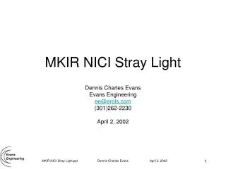
Optical Analysis and Stray Light Evaluation Dennis Charles Evans 16 November 2001 Optical Analysis & Stray Light Evaluation
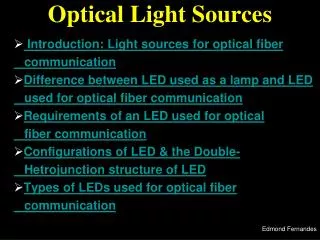
ZEMAX Optical Layout • ISAL prescription from TMA62 write-up • Checked against customer supplied ZEMAX • Optical Sensitivities • Basic Sensitivity • Active Secondary (5-dof) • Stray Light Baffle Layout • Spectrograph Enclosure and Insertion • Views from the Detector • Solar Flux • Open Items Optical Analysis & Stray Light Evaluation
ZEMAX Optical Layout • ISAL prescription from TMA62 write-up • Checked against customer supplied ZEMAX Optical Analysis & Stray Light Evaluation
Optical Sensitivity Basic Sensitivity Individual Element Increments of 0.001 mm or degree to 0.016 MF Limit (RMS Spot Radius) (0.002837÷0.005000)*2 = 0.32194276 Active Secondary Five degree-of-freedom Dx, Dy, Dz, Tx, Ty Limits on Secondary ± 1 mm or degree Limits on Elements ± 0.256 mm or degree Optical Analysis & Stray Light Evaluation
Key Tolerance Comparison Optical Analysis & Stray Light Evaluation
Basic Sensitivity (limited to 0.005 RMS Radius) TETX TETY Tilt about X & Y 5=Primary 0.000335 deg ×3600 arc-sec/deg = 1.206 arc-sec TTHI Thickness 4-6; 0.000802 mm TRAD Radius of Curvature 5 0.001604 mm (= same effect as thickness change) TIRX TIRY Sag (Tilt) Across Lens 5 0.011705 mm TSDX TSDY Surface Decenter 5 0.014518 mm TEDX TEDY Element Decenter 5 0.014518 mm TETX TETY Tilt about X & Y 8=Secondary 0.001515 deg ×3600 arc-sec/deg = 5.454 arc-sec TTHI Thickness 7-9; 0.000602 mm TRAD Radius of Curvature 8 0.001828 mm TIRX TIRY Sag (Tilt) Across Lens 8 0.011261 mm TSDX TSDY Surface Decenter 8 0.014658 mm TEDX TEDY Element Decenter 8 0.014658 mm TETX Tilt about X & Y 17=Fold Flat 0.008217 deg ×3600 arc-sec/deg = 5.454 arc-sec TETY Tilt about X & Y 17 0.011621 deg ×3600 arc-sec/deg = 5.454 arc-sec TTHI Thickness 16-18; 0.018010 mm TRAD Radius of Curvature 17 insensitive at 0.256 change TIRX Sag (Tilt) Across Lens 17 0.150454 mm TIRY Sag (Tilt) Across Lens 17 0.106387 mm TSDX TSDY Surface Decenter 17 insensitive at 0.256 change (0.002884) TEDX TEDY Element Decenter 17 insensitive at 0.256 change (0.002884) TETX TETY Tilt about X & Y 22=Tertiary 0.016927 deg ×3600 arc-sec/deg = 60.9372 arc-sec TTHI Thickness 21-23; 0.016919 mm TRAD Radius of Curvature 22 0.031079 mm TIRX TIRY Sag (Tilt) Across Lens 22 0.199252 mm TSDX TSDY Surface Decenter 22 insensitive at 0.256 change (0.003732) TEDX TEDY Element Decenter 22 insensitive at 0.256 change (0.003732) TETX TETY Tilt about X & Y 32-33=Filter insensitive at 0.256 change (0.002886) TTHI Thickness 21-23; 0.016919 mm TRAD Radius of Curvature 22 0.031079 mm TIRX TIRY Sag (Tilt) Across Lens 22 0.199252 mm TSDX TSDY Surface Decenter 22 insensitive at 0.256 change (0.003732) TEDX TEDY Element Decenter 22 insensitive at 0.256 change (0.003732) TTHI Filter to Image 36-37 0.136618 mm (Image Plane is compensator for fast analysis) Optical Analysis & Stray Light Evaluation
Active Secondary Sensitivity |------------ Minimum ------------| |------------ Maximum ------------| Type Value MF Change Value MF Change (Primary Mirror) Thickness tolerance on surface 4 TTHI 4 6 -0.033610 0.005000 0.002163 0.033112 0.005000 0.002163 Thickness 8: 1.00001E+000 -1.00001E+000 Radius tolerance on surface 5 TRAD 5 -0.066773 0.004566 0.001730 0.066242 0.005000 0.002163 Thickness 8: 1.00001E+000 -1.00001E+000 Tilt X tolerance on surfaces 5 through 5 (degrees) TETX 5 5 -0.185670 0.005000 0.002163 0.185670 0.005000 0.002163 Parameter 2 on Surface 7: 9.12416E-002 -9.12419E-002 Parameter 3 on Surface 7: -1.87703E-001 1.87703E-001 Tilt Y tolerance on surfaces 5 through 5 (degrees) TETY 5 5 -0.185720 0.005000 0.002163 0.185720 0.005000 0.002163 Parameter 1 on Surface 7: -9.12903E-002 9.12680E-002 Parameter 4 on Surface 7: -1.87754E-001 1.87754E-001 (Fold Flat) Thickness tolerance on surface 16 TTHI 16 18 -0.256000 0.004764 0.001927 0.256000 0.004764 0.001927 Thickness 8: 1.74322E-001 -1.87717E-001 TIRX 17 -0.256000 0.004388 0.001551 0.256000 0.004388 0.001551 Parameter 1 on Surface 7: -5.13796E-001 5.13786E-001 TIR Y tolerance on surface 17 TIRY 17 -0.222637 0.005000 0.002163 0.222637 0.005000 0.002163 Parameter 2 on Surface 7: 6.31916E-001 -6.31897E-001 Tilt X tolerance on surfaces 17 through 17 (degrees) TETX 17 17 -0.017196 0.005000 0.002163 0.017196 0.005000 0.002163 Parameter 2 on Surface 7: 6.31902E-001 -6.31891E-001 Tilt Y tolerance on surfaces 17 through 17 (degrees) TETY 17 17 -0.024319 0.005000 0.002163 0.024319 0.005000 0.002163 (Tertiary Mirror) Tilt X tolerance on surfaces 22 through 22 (degrees) TETX 22 22 -0.055298 0.005000 0.002163 0.055298 0.005000 0.002163 Parameter 2 on Surface 7: -1.00001E+000 1.00001E+000 Tilt Y tolerance on surfaces 22 through 22 (degrees) TETY 22 22 -0.055298 0.005000 0.002163 0.055298 0.005000 0.002163 Parameter 1 on Surface 7: 1.00001E+000 -1.00001E+000 Optical Analysis & Stray Light Evaluation
Stray Light Baffle Layout Optical Analysis & Stray Light Evaluation
Spectrograph Enclosure and Insertion Optical Analysis & Stray Light Evaluation
Views from the Detector Optical Analysis & Stray Light Evaluation
Solar Flux Concentrations inside Instrument • Solar Flux = 1 SC = .1367 watt.cm-2 = 1367 watt.m-2 Optical Analysis & Stray Light Evaluation
Open Items&Concerns Optical Analysis & Stray Light Evaluation
Open Items • Shade angle (<30o?) and Barrel Baffle length • Baffle edge finish (Forward Ring) • Cleanliness, especially of Primary Mirror • Aft Optics Baffles (Mostly black paint) • MLI outer layer vs. mission length • Reverse views • AutoCAD Photo Ray Trace • reverse ray trace, TMA62 • Focal plane • parfocalization (filter thickness) • S/G placement • behind focal plane? • center mounted • ASAP diffuse scatter model • (Friday PM – Next Week) Optical Analysis & Stray Light Evaluation
Mission Unique Concerns: • No mission unique concerns have been observed. • Stray light issues are manageable using proven baffling techniques that have been successfully demonstrated on flight missions. • Analysis done too early in the design cycle is likely to give false confidence (analytical design is better than real design). Optical Analysis & Stray Light Evaluation
Central Obscuration • Minimum possible - about 5% (Shadow of Secondary) • Current minimum design to keep direct light from Focal Surface 1 - about 15% • Maximum practical limit to keep direct light from inner baffle interior and front lip - slightly less than 25% Optical Analysis & Stray Light Evaluation
Stray Light Issues • Similarity to flight instruments shows successful design is possible • HST, FUSE, COBE-DIRBE, IUE, OAO • Similarity to flight instruments shows design flaws are possible that will not be detected by stray light analysis, but by careful design, inspection, and testing. • HST - Door reflections • DIRBE - Barrel Baffle side wall single bounces. • IUE/OAO - Pinhole leaks into aft optics assemblies; bolt head locations. • Design & Analysis Similarity • SIRTF - IRAC • WIRE (minor changes make orders of magnitude stray light differences) • GOES Earth Limb Sensor (light leaks around filters and side wall reflections) • MODIS - Stray light in calibrator designs, not instrument designs Optical Analysis & Stray Light Evaluation
Focus Drive Mechanism • Definition of acceptable image size needs to be reviewed. • RMS radius of 0.005 mm may be to conservative for a pixel limited performance instrument. • Range of motions used were +/- 1 mm and degree. • The Displacement motions may be effectively increased to 5 or 10 mm for some corrections. • Tolerance analysis so far is only with two elements at a time and has not included Image Plane tilts. Optical Analysis & Stray Light Evaluation
View from the detector inspection is important. • Fold Flat throat can be illuminated by sky. • Fold flat throat design as in this study may not allow AFT star tracker • AFT optics baffles and black surfaces • Baffles not designed yet • Black paint has been known to cause CTE changes in GFRP structures. Optical Analysis & Stray Light Evaluation