Download
1 / 25
250 likes | 332 Vues
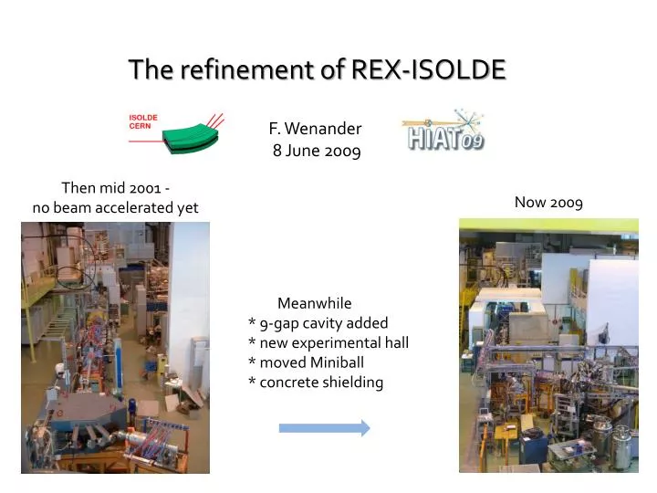
The refinement of REX-ISOLDE F. Wenander 8 June 2009. Then mid 2001 - no beam accelerated yet. Now 2009. Meanwhile * 9-gap cavity added * new experimental hall * moved Miniball * concrete shielding. Harvest incl. 2008. …and beams accelerated.

E N D
The refinement of REX-ISOLDE F. Wenander 8 June 2009 Then mid 2001 - no beam accelerated yet Now 2009 Meanwhile * 9-gap cavity added * new experimental hall * moved Miniball * concrete shielding
Harvest incl. 2008 …and beams accelerated 8Li3+(2006),9,11Li2+(2004),9Li2+(2005), 10,11Be3+,4+(2006), 11,12Be3+,4+(2005), 10C3+(2008), 17F5+(2004), 17F5+(2007),24-29Na7+,29,31Mg9+(2006), 30Mg9+(2007), 30Mg7+(2008), 30,31Mg9+(2007),28,30,32Mg8+, 61,62Mn15+(2008), 61,62Fe15+(2008), 68Ni19+(2005), 70Cu19+(2008), 67,69,71,73Cu19+,20+,20+,19+(2006), 68,69,70Cu19+,20+,19+(2005), 74,76,78Zn18+(2004), 80Zn21+(2006), 70Se19+(2005),88,92Kr21+,22+,96Sr23+(test), 96Sr27+(2007), 108In30+(2005),106,108Sn26+(2006), 108Sn27+(2005), 110Sn30+(2004), 100,102,104Cd24+,25+,25+(2008), 122,124,126Cd30-31+(2004), 124,126Cd30,31+(2006), 138,138,140,142,144Xe34+, 140,142,148Ba33+,33+,35+(2007), 148Pm30+, 153Sm28+, 156Eu28+, 184,186,188Hg43+,43+,44+(2007), 182,184,186,188Hg44+,44+,44+,45+(2008),202,204Rn47+(2008) radioactive stable 2009 24 different radioactive elements and over 60 isotopes accelerated 9 experiments 171 shifts (8 h) Further info at http://isolde.web.cern.ch/ISOLDE/REX-ISOLDE/index.html F. Wenander HIAT 2009
Machine layout Electron beam ion source * 1+ ions to n+ * Super conducting solenoid, 2 T * Electron beam <0.4 A, 3-6 keV * Breeding time 3 to >200 ms Machine layout REXEBIS MASS SEPARATOR Optional stripper for beam cleaning ISOLDE ISOLDE beam Primarytarget 7-GAP RESONATORS 9-GAP RESONATOR IH RFQ 1.4 GeV protons from PSB <3E13 p/pulse Rebuncher 60 keV 0.3 MeV/u 3.0 MeV/u 2.2 MeV/u 1.2 MeV/u REXTRAP Experiments Penning trap * Longitudinal accumulation and bunching * Transverse phase space cooling * 3 T solenoid field + quadratic electrostatic potential + RF cooling * Buffer gas filled (5E-4 mbar) * Cooling time ~20 ms Linac Type normal conducting 6 accelerating cavities Length 11 m Freq. 101 MHz (202 MHz for the 9GP) Duty cycle 1 ms 100Hz Energy 300 keV/u, 1.2-3 MeV/u (variable) A/q max. 4.5 F. Wenander HIAT 2009
Efficiency = Trap+EBIS+REX mass separator Present performance 23Na9+ * * REX low energy= 2-16 % * Depends on: mass, A/q, experience * Linac transmission x 0.6-0.85 * A<20 ions still difficult * Heavy ions low efficiency: charge exchange? heating losses? under investigation broader CSD? 39K9+ 65Cu19+ 23Na7+ 114Cd25+ 26Mg7+ 55Mn15+ 87Rb17+ 133Cs32+ 104Cd25+ 70Cu19+ 186Hg44+ 181Ta40+ 205Tl42+ Elements from 2008/2009 188Hg45+ 204Rn47+ * Trap time excluded; same as the breeding time (at least 20 ms) * Tbreed depends on A/q & injection condition (High efficiency -> short breeding time) * Half-lives down to some 10 ms * Closed shell * F. Wenander HIAT 2009
All this is standard operation… (although manpower consuming) …the following is over-drive
Time structure * ISOLDE * REX 14x1.2 s Proton bunch to ISOLDE Proton bunch NOT to ISOLDE t (s) 800 ms 2.4 s Target and ion source release t (s) 200 ms Collection Cooling Bunching RFQ coolerpulsed mode t (ms) * RFQ cooler recently installed at ISOLDE * Before REXTRAP -> beam gymnastics * Pulsed or CW mode F. Wenander HIAT 2009
200 ms Collection Cooling Bunching RFQ coolerpulsed mode t (ms) REXTRAP mass resolving mode Pre-centering Quadrupole excitation cyclotron URF De-centering 60 ms Mass-selective re-centering - + Dipoleexcitation magnetron 20 ms - + + + - 120 ms - - + t (ms) • Mass separation operation cycle • cool down the ion cloud • shift out the ion cloud with a dipolar excitation • selectively re-centre the desired species F. Wenander HIAT 2009
Isobaric mass resolution S. Sturm, Master Thesis, Universität Heidelberg (2007) Already: isobaric separation inside REXTRAP previously proven only trap, low efficiency, suppression unknown Now: measured after the REXEBIS -> trap cooling sufficient contamination suppression 20-50 (lower limit) FWHM = 15 Hz Resonance curve for 133Cs Mass resolution = 2.3e4 96% suppression From local ion source Resonance curve for 39K Mass resolution = 3.0e4 REXTRAP + REXEBIS transmission 2.5 % 98% suppression ISCOOL used as pre-buncher and cooler F. Wenander HIAT 2009
Mass resolution Pulsed REXTRAP barriers Injected ions Efficiency Resolution Space charge effects > 1E6 ions/pulse Frequency shifts – can be compensated for Peak broadening -> reduced mass resolution Limit includes stable contaminants • Transmission increased a factor 10 • Depending on: mass resolution • suppression factor HRS – High Resolution Separator 39K from RFQ cooler HRS mass resolving power HRS mass resolving power Injection Extraction Compare with 17% without mass resolution F. Wenander HIAT 2009
Multiple peaks sometimes visible Mass separation reservations • Apart from efficiency and space charge... • 1. Total cycle time 100 t0 200 ms Limits the use of nuclides with halflives < 100ms • 2. Setup not evident – at least 8 h; slowly gaining experience • 3. Multiple peaks appearing (for single element) • 4. Processes in trap not fully understood Triple peaks Final test to come: isobarically contaminated radioactive beam TOF after trap NB: only one beam component (39K) F. Wenander HIAT 2009
Undesired for: 80Zn (t1/2=537 ms) – also got 80Ga (Ttrap=80 ms, Tbreed=78 ms) In-trap decayfor better or for worse The idea: Let easily produced elements decay in REX low-energy part prior to acceleration to provide post-accelerated beams of difficultly produced elements previously used at ISOLTRAP; A. Herlert et al., New J. Phys. 7 (2005) 44 Doppler corrected Coulex spectra (Miniball) J. Van de Walle Tested first time at REX-ISOLDE with 61Mn (T1/2=675 ms; 1.7x10⁶ atoms/s) Energy [keV] Ttrap Tbreed Result 200-1100 ms 28 ms no Fe detected at Miniball 300-1100 ms 298 ms 57(7)% Fe detected agrees with predictions F. Wenander HIAT 2009
Mn -> Fe in-trap decay Why not working in REXTRAP? SIMION simulations show that 90% of the recoiling daughter ions are trapped in REXTRAP Why not working in REXTRAP? F. Ohlsson’s Diploma thesis Chalmers university of Technology 2007 Fraction of daughter depends on 1. X+ -> β+ -> X0 X+ -> β- -> X++ 2. half-life + trapping and breeding time 3. ion recoil energy and distribution (Fermi vs Gamow–Teller decay) 4. trapping potentials (trap and EBIS) 5. Auger and shake-off effects 6. n+ recombination time M. Beck, ‘WITCH internal report…’, 7 May 2007
Future in-trap decay applications * Choice: decay in trap or in EBIS * Prefer decay in trap to EBIS No linac A/q rescaling No disturbing residual A/q-peaks No ion losses due to electron heating Further test in July • Limitations • Good yield from ISOLDE • Reasonable t1/2 mother: 10 ms to 2 s • - decay -> daughter 2+ or n+ charged • + decay -> daughter neutral or n+ • Daughter recoil energy limited trapping potentials in trap (100-200 V) and EBIS (300-400 V) New! Prospective new beams for REX-ISOLDE produced with - in-trap decay. F. Wenander HIAT 2009
M. Hass et al., NPA 414, 316 (84) Polarized beams * Polarization - ion‐surface interactions (no bulk‐effects influences) * Atomic polarization nuclear polarization * Nuclear polarization degree PI: higher polarization level at higher I (nuclear spin) faster “saturation” at lower I (fewer foils needed) strong velocity dependence Induced Nuclear Polarization using Multi Tilted Foils Previously shown for 51VPI > 10(1) % at β = 4.6% Physics * Transfer reactions * Decay spectroscopy First tests with 27Na 5/2+ or Coulex 21Ne 3/2+ F. Wenander HIAT 2009
possible positions Mobile tilted foil setup Modular foil stack 1. Adjust intermediate foil distance with spacers 2. Adjust number of foils 3. Adjust beam inclination angle 4. Ladder with three different foil configurations Aperture size first version 20*14 mm second version 30 to 35 mm large axis Foil type laser ablated C , 4 ug/cm2 from TU Munich pA beam flux -> no life-time problems REX-ISOLDEbeam diagnostics box Goal – parameter scan F. Wenander HIAT 2009
Constraints and Alternatives 1.Tilted foil -> charge state distribution -> low overall efficiency (or install foils after all magnetic elements) 2. Post-acceleration after polarization? Noble-gas like charge states 3. Beam energy for optimal polarization should coincide with charge state distribution for magic number Equilibrium charge fraction of ion after passage through a carbon foil as function of exit energy K. SHIMA et al., Atomic data and nuclear data tables, 1992, vol. 51, no2, pp. 173-241 * b-NMR setup from HMI Berlin * To be installed after the linac -> beam energy 0.3 to 3 MeV/u * nuclear structure (moments, reactions …)nuclear methods in the solid-state physicsbiophysics etc. … F. Wenander HIAT 2009
Diamond detector tests Wish list - 1st phase current amplification beam profiler / beam position <1 pA beam intensity <0.5% energy measurement - 2nd phase TOF cavity phase measurements pCVD, 10x10 mm2, 500 um thick plated with square 8x8 mm2 Al electrodes thickness of 25 nm sCVD, 5x5 mm2, 500 um thick plated with 3 mm diameter Au electrodes thickness of 500 nm Manufacturer: Diamond Detectors Ltd own contact layers Test ‘outsourced’ to: E. Griesmayer, ATLAS/CERN and Bergoz Instrumentation, St Genis, France F. Wenander HIAT 2009
sCVD results + Very low noise level (< 1mV) -> Noise discrimination easy + Particle counting up to 1E4 part/s (duty factor => ~1E7 part/s) Signal height, not charge integration Tscale=10 ns/div Vscale=50 mV/div • + ~1% energy resolution 12C4+ 1.9 MeV/u • sCVD with 1000 V bias • Cases with worse resolution • Solved with polarity change • Space charge? Charge trapping? • Expensive – 3 kCHF for 5x5 mm2 Single pulse example, +500 V bias Pulse height 109 mV Pulse width 7.7 ns F. Wenander HIAT 2009
pCVD results 1. fluctuating leakage current (tens pA to nA) -> current amplification mode not viable 2. signal height polarity and time dependent -> counting problems 3. signal size decreases with beam loading / time -> position tuning difficult; always better at fresh pixel -> counting problems Single pCVD pulse Tscale=5 ns/div Vscale=5 mV/div C. Tuve et al., Diamond and Related Materials 15 (2006) 1986-1989 Reasons? *charge trapping * polarization * structural defects * contact layer *… ‘High-Resolution Energy and Intensity…’. E. Griesmayer et l., CERN BE Note, 2009 , tbp F. Wenander HIAT 2009
Last word Stable 23Na+cwfrom HRS Modest ebeamcurrent Tperiod=20 ms Onlyadjustedc Tbreeding=11-13 ms NB! M. Pasini talk on HIE-ISOLDE Repetition rate 50 Hz: 2.5 nA -> 1.5E10 ions/s -> 3E8 ions/pulse with > 5% eff Worse for RI discharges recombination Hot from the lab 23Na7+ Thanks to A. Gustafsson, D. Voulot, J. Van de Walle, R. Scrivens, E. Griesmayer, T. Aumeyr… Wait for the 2nd generation! F. Wenander HIAT 2009
Mass separation in REXTRAP - Space-charge effects • Frequency shifts • Peak broadening Gas pressure control = 5 V 2.5e6 ions/bunch 2.5e6 ions/bunch Gas = 5V 2e7 ions/bunch Gas = 7.5 V
C. Tuve et al., Diamond and Related Materials 15 (2006) 1986-1989 Did we have the same for the energy measurement?
16O8+ 16O7+ 50 ug/cm2carbon foil 4 ug/cm2carbon foil 8Li3+/16O6+ IHS RFQ 3MeV/u 300keV/u 8Li3+/16O6+ A/q selectionB dipole field Energy loss + some stripping of 16O Conventional charge stripping Larger energy loss for 16O -> enters IHS at the wrong energy -> lower transmission Double stripping Can we make use of the different energy loss through a stripping foil to eliminate selectively heavy contaminant? (8Li run Oct. 2006) • 8Li/16O ratio increased by a factor 13 (expected a factor 3 with single stripping foil) • Beam intensity decreased by a factor 3 -> can only be used in case of sufficiently intense beams
Time Structure Trapping 1 shift at REX = 19 min actual measuring time Charge Breeding Post Acceleration • Bunched beam : high instantaneous rate ! • deadtime … • Good signal/background …
200 ms Collection Cooling Bunching RFQ coolerpulsed mode t (ms) REXTRAP mass resolving mode Pre-centering Quadrupole excitation cyclotron URF De-centering 60 ms Mass-selective re-centering - + Dipoleexcitation magnetron 20 ms - + + + - 120 ms - - + t (ms) FWHM 25 us (to 400 us) 50 ms Charge breeding REXEBIS t (ms) Linac RF on for acceleration Ion hold-up time (in this case) = 100 ms (average) +200 ms +50 ms t (us) 780 usBeam on 780 usBeam off 3 ms