Download
1 / 47
510 likes | 696 Vues
Power Converters and Power Quality. Karsten KAHLE, CERN karsten.kahle@cern.ch. References. EN 50160 (2010) Voltage characteristics of electricity supplied by public distribution systems IEC 61000 Electromagnetic compatibility :

E N D
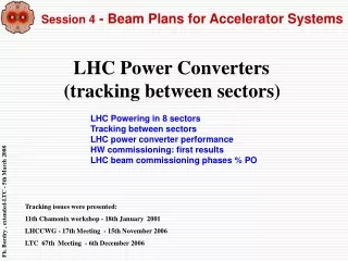
Power Converters and Power Quality Karsten KAHLE, CERN karsten.kahle@cern.ch
References EN 50160 (2010) Voltage characteristics of electricity supplied by public distribution systems IEC 61000 Electromagnetic compatibility: IEC 61000-2-2 Compatibility levels for low frequency conducted disturbances and signalling in public low voltage (LV) power supply systems IEC 61000-2-4 Compatibility levels in industrial plants for low-frequency conducted disturbances IEC 61000-2-12 Compatibility levels for low frequency conducted disturbances and signalling in public medium voltage (MV) power supply systems IEC 61000-3-4 Limitations of emissions of harmonic currents in LV power supply systems for equipment rated > 16A IEC 61000-3-6 Assessment of emission limits for distorting loads in MV and HV power systems IEC 61000-4-7 General guide on harmonics and interharmonics measurements ....for power supply systems and equipment connected thereto VEÖ-VSE- CSRES-VDE Technical rules for the assessment of public power supply compatibilities (in German); VEÖ - Verband der ElektrizitätswerkeÖsterreichs, VSE -VerbandSchweizerischerElektrizitätswerke, CSRES – Ceske sdruzeniregulovanychelektroenergetickychspolecnosti, Forum Netztechnik im VDE (2007) and technical annex document (2012) CAS 2004, Warrington Electrical Network and Power Converters, H. U. Boksberger, PSI CERN, ref. EDMS 113154 Main Parameters of the LHC 400/230 V Distribution System https://edms.cern.ch/file/113154/2/LHC-EM-ES-0001-00-20.pdf
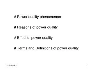
Power Converters and Power Quality • What is Power Quality? • Classification of disturbances • Statistics (example CERN) • Additional power quality considerations • Electrical networks and pulsating power • Systems without energy storage • Systems with integrated energy storage • Conclusions
Power Converters and Power Quality • What is Power Quality? • Classification of disturbances • Statistics (example CERN) • Additional power quality considerations • Electrical networks and pulsating power • Systems without energy storage • Systems with integrated energy storage • Conclusions
Classification of disturbances DIP SWELL
MAINS FAILURES • Causes: • thunder-storms • short-circuits inside CERN • Emergency Stop operation • Consequences: • accelerator stop Classification of disturbances DIP SWELL
VOLTAGE DIP / SWELL MAINS FAILURES • Causes: • sudden change of load, inrush • short-circuits inside & outside CERN • thunder-storms • Causes: • thunder-storms • short-circuits inside CERN • Emergency Stop operation • Consequences: • accelerator stop • Consequences: • sometimes accelerator stop Classification of disturbances
VOLTAGE DIP / SWELL MAINS FAILURES • Causes: • sudden change of load, inrush • short-circuits inside & outside CERN • thunder-storms • Causes: • thunder-storms • short-circuit inside CERN • Emergency Stop operation • Consequences: • accelerator stop • Consequences: • sometimes accelerator stop TRANSIENTS • Causes: • switching capacitor banks ON (SVC’s) • thunder-storms • Consequences: • failure of electronics Classification of disturbances
VOLTAGE DIP / SWELL MAINS FAILURES • Causes: • sudden change of load, inrush • short-circuits inside & outside CERN • thunder-storms • Causes: • thunder-storms • short-circuit inside CERN • Emergency Stop operation • Consequences: • accelerator stop • Consequences: • sometimes accelerator stop HARMONICS • Causes: • non-linear loads • (power converters, computer centers, PC’s) • Consequences: • malfunctioning of electronics • overload of Neutral conductor Classification of disturbances TRANSIENTS • Causes: • switching capacitor banks ON (SVC’s) • thunder-storms • Consequences: • failure of electronics
Power Converters and Power Quality • What is Power Quality? • Classification of disturbances • Statistics (example CERN) • Additional power quality considerations • Electrical networks and pulsating power • Systems without energy storage • Systems with integrated energy storage • Conclusions
100% = nominal voltage red colour: major events (accelerator stop) Power quality statistics (CERN network) Voltage disturbances 400 kV …. long-term
100% = nominal voltage red colour: major events (accelerator stop) Power quality statistics (CERN network) Voltage disturbances 18 kV …. long-term
100% = nominal voltage red colour: major events (accelerator stop) Power quality statistics (CERN network) Voltage disturbances 400 V …. long-term
Power quality statistics (CERN 400 V networks) IEC 61000-2-2, class 2 IEC 61000-2-2, class 1 UPS
Power quality statistics The MAJORITY of power quality issues is caused insideCERN. The MAJORITY of network disturbances has no consequences.
Power Converters and Power Quality • What is Power Quality? • Classification of disturbances • Statistics (example CERN) • Additional power quality considerations • Electrical networks and pulsating power • Systems without energy storage • Systems with integrated energy storage • Conclusions
Specification of immunity of electrical equipment Before constructing the LHC, CERN specified the immunity levels for all electrical equipment. This internal standard intends to assure a certain minimum immunity of equipment, with the objective to significantly increase MTBF of the LHC. Unfortunately, it shows now during LHC operation, which equipment does not sufficiently respect this standard. In particular, voltage dips and voltage swells remain the main power quality issues for LHC. … long-term “Main Parameters of the LHC 400/230 V Distribution System” Typical disturbances Standardised CERN immunity levels for voltage variations https://edms.cern.ch/file/113154/2/LHC-EM-ES-0001-00-20.pdf
Propagation of external disturbances into a distribution network Propagation of external asymmetrical disturbances into a network depends on the combination of transformer vector groups (e.g. 400 kV voltage dips going into CERN network): Single phase dip, -50% in phase R Double-phase dip (-50% in phases R and T, healthy phase = S) Principle of propagation Single-phase dip Double-phase dip
Flicker Flicker: Impression of unsteadiness of visual sensation induced by a light stimulus whose luminance … fluctuates with time. Voltage fluctuation: Changes of r.m.s. voltage evaluated as a single value for each successive halfperiod of the source voltage Short-term flicker indicator Pst: Flicker severity evaluated over a short period (in minutes); Pst = 1 is the conventional threshold of irritability Long-term flicker indicator Plt: Flicker severity evaluated over a long period (a few hours) using successive Pst values relative voltage change ΔU/U Number of voltage changes per minute Note: 1200 voltage changes per minute = 10 Hz flicker Ref. IEC 61000-3-3 fig. 4 Flicker caused by power converters for accelerators • Some thoughts: • Flicker limits are based on the empiric definitions of the human eye’s sensitivity to luminance fluctuations. • Flicker limits are important contractual parameters at the point of connection to the external grid, to be strictly respected! • Inside the physics laboratory, the irritating effects of flicker can be reduced by strictly separating general services (lighting) and power converter networks.
Effects of pulsating loads on external networks External 400 kV network 400 kV network 230 MW peak - Pulsating reactive power is compensated within CERN (SVC’s) - Pulsating active power is supplied by the 400 kV network Δ U (400 kV) due to SPS: < 0.6 % pk-pk*) Δ f (400 kV) due to SPS: 5 … 25 mHzpk-pk*) *) depending on 400 kV network configuration (and its Scc) Example: CERN SPS In general: Reactive power variations cause voltage variations (flicker) Active power variations cause frequency variations in the grid 130 kV network
Electromagnetic environment classes acc. IEC 61000-2-4 Class 1: Protectedsupplies for compatibility levels lower than those on public networks … for very sensitive equipment. Class 2: Environments of industrial and other non-public power supplies … and generally identical to public networks. Class 3: Industrial environments, in particular when – a major part of the load is fed through converters; -> Hey, that’s a particle accelerator! – loads vary rapidly. -> Yes, a particle accelerator! – …. Power converters for particle accelerators represent the roughest type of load, comparable to heavy industry such as large arc furnaces, rolling mills etc. (class 3). However, to operate them correctly and with the required precision, power converters for particle accelerators require compatibility levels sometimes better than the most sensitive equipment (class 1). What do these three classes actually mean?
Power Converters and Power Quality • What is Power Quality? • Classification of disturbances • Statistics (example CERN) • Additional power quality considerations • Electrical networks and pulsating power • Systems without energy storage • Systems with integrated energy storage • Conclusions
Power quality improvement by SVC’s *) Example: SVC for SPS (TCR 150 Mvar, -130 Mvar harmonic filters) Building for thyristor valve, cooling and control room Thyristor controlled reactors Harmonic filters *) FACTS = Flexible AC Transmission Systems
Power quality improvement by SVC’s *) Static Var Compensators (SVC’s) - variable Mvar generation -> p.f. ~ 1 - variable voltage support (stabilisationUref) - harmonic filtering Capacitor banks (=harmonic filters) - constant Mvar generation, p.f. ≠ 1 - constant voltage support (constant voltage increase) - harmonic filtering - always requires tuning to control resonances! Thyristor controlled reactors (TCR) harmonic filters harmonic filters *) FACTS = Flexible AC Transmission Systems
a) Reactive power compensation Thyristor power converters consume (pulsating) active and reactive power. Without SVC: - load reactive power taken from the network - transmission and distribution system needs to be rated for apparent power S - reactive power variations cause flicker - contractual power factor at grid connection point - reactive power consumption costs money! With SVC: - load reactive power is compensated locally - lean transmission and distribution system - reduced transmission losses - disturbing effects of pulsating reactive and active power eliminated (no flicker) S Q Q -QSVC S’ P P
Reactive power compensation reactive power 50% SPS SPS power converters 90 Mvar filters -130 Mvar TCR 150 Mvar
Reactive power compensation Example: SVC BEQ3 for SPS Active power consumedby load (SPS) Reactive power consumed by load (SPS) Reactive power generated by SVC Reactive power taken from EDF is almost zero! Active and reactive power
b) Voltage stabilisation - during each power pulse, the voltage of the network decreases - periodic power cycling causes unwanted periodic voltage drops (flicker) - the principal cause: changingMvars flowing through the inductance of the power network Cables 18 kV Transformer 400/18 kV Network 400kV R + jX R + jX R + jX Voltage drop 1 + Voltage drop 2 + Voltage drop 3 U = RI cos + XI sin load U source This term is the principal responsible for voltage variations due to (pulsating) reactive power of the load: Inductive load -> voltage drop Capacitive load -> voltage increase!
b) Voltage stabilisation How to keep the network voltage constant during the power pulses? Solution: SVC generates a specific pulse of reactive power, to compensate for the unwanted drops caused by pulsating active and reactive power of the load. reactive power generated by SVC active power consumed by load reactive power consumed by load network short-circuit power • With of the supplying network Nota: An SVC cannot assure perfect Mvar compensation and perfect voltage stabilisation at the same time. We need to allow for small variations of reactive power to correct the disturbing effects of active power variations.
b) Voltage stabilisation How to vary the reactive power generation of an SVC? Variant 1: Variation in discrete steps Variant 2: Capacitor bank and TCR (continuous variation between 0 and max.) mechanical switches or thyristors C1 C2 C3 Capacitance step size, example: 22 21 20 thyristor valve (bi-directional) capacitor bank (always ON) thyristor controlled reactor (TCR)
b) Voltage stabilisation How can an SVC generate a pulse of (capacitive) reactive power? Let’s take variant 2 from previous page: Capacitors and TCR (continuous variation between 0 and max. reactive power generation) QTCR TCR C Limitations of SVC technology: - Response time 50-100 ms, hence unsuitable for correction of fast transient network disturbances - Mvar output decreases with network voltage, hence unsuitable for voltage support at low system voltage QSVC = QC + QTCR QC Typically, an SVC should stabilise the network voltage to ±1%, even for fast load changes
b) Voltage stabilisation 18 kV network voltage Example SVC for SPS Voltage variations @18kV: Without SVC: -14% With SVC: ±0.75% +/- 0.3 % +/- 0.75 % 18 kV voltage response Typical SVC response time: 50–100ms
c) Harmonic filtering Example: SVC for SPS First parallel resonance with network (107 Hz) is mastered by 100 Hz and 150 Hz filters Tuned to typical harmonic frequencies of 6p and 12p thyristor converters (250, 350, 550, 650 Hz) Feeder from 18 kV substation Damped high-pass filters 950 Hz and 1050 Hz 1050 Hz filter can be disconnected to operate SVC with -112 Mvar instead of -130 Mvar (reduced SVC losses) Harmonic performance: indiv. harm. max. 0.5 % THD(18 kV) max. 0.75 % Comparison: Limit = 8% for IEC 61000-2-2 class 2 TCR rated 150 Mvar (filters -130 Mvar) to allow 20 Mvar inductive SVC output in case of high network system voltage SVC split in 3 groups due to circuit breaker limits for capacitive switching
Summary of SVC performance Example: SVC for SPS The reactive power values in the first line concern one system (50% of SPS). For total SPS, multiply by 2.
Most common harmonic filter configurations for SVC’s 50 Hz Harmonic current High-pass filter - 850 Hz and above C-type filter - reduced 50 Hz losses - requires add. type of C - typically for 100 and 150 Hz L-C-type filter - for 250, 350, 550 and 650 Hz In all configurations, the capacitor banks are in double-star connection, star-points not connected to earth. Star connection is preferred to delta, for better capacitor protection, and to limit the need for series connection of capacitor units.
TCR configuration for SVC’s Delta connection of reactors: - to trap the triple harmonics in the delta (reduced harmonics from the network) - it’s cheaper to build thyristor valves with high voltage than high current (thyristor series connection) - in unearthed star connection, the starpoint would move Losses of SVC technology: - at zero Mvar output, the TCR current cancels out the capacitive current of harmonic filters (unnecess. losses!) - overall, the relative losses of an SVC are quite small: harmonic filters = 0.1% TCR + thyristors = 0.4% (of total Mvar rating) Thyristor controlled reactors (HV part) Typical TCR control strategy
Design considerations for SVC’s for particle accelerators 1. Expected performance? - Controlling DC magnet current to ppm precision (and minimise ripple), requires clean AC supply! 2. Voltage level - Typically, SVC’s are connected to MV network 10 – 36 kV. - Var compensation at LV level 400 V not recommended (changing network configurations, resonances …) 3. Choice of technology - Harmonic filters (could be switched in groups, depending on load situation), with thyristors or switches - SVC: Harmonic filters, combined with thyristor controlled reactors, compensation of reactive power - STATCOM: compensation of active and reactive power 4. Electrical location - Where is the optimum connection point for best SVC performance? 5. Rating - Minimum Mvar rating of harmonic filters and TCR: to compensate for voltage variations due to Q and P - TCR and harmonic filters do not need to have identical Mvar rating; SVC could also be asymmetrical 6. Harmonic filter design - Typical spectrum of power converters: n*p ±1, with n = 1, 2, 3 and p = 6 or 12-pulse -> F5, F7, F11, F13 and HF filters - Connecting capacitor banks: parallel resonance with network: , then F2 or F3 might be required
SVC – how does it look like? Filter reactors Thyristor valve 18 kV, 2800 A TCR reactors (50 Mvar / ph) Cooling plant for thyristor valve Filter capacitors Harmonic filter protection
Power Converters and Power Quality • What is Power Quality? • Classification of disturbances • Statistics (example CERN) • Additional power quality considerations • Electrical networks and pulsating power • Systems without energy storage • Systems with integrated energy storage • Conclusions
Rotating machines Decoupling of cycling pulses of active and reactive power from the network (e.g. BNL and CERN) CERN-PS BNL-AGS courtesy: I. Marneris • Decoupling: • From network: around 6 MW peak • The load: 45 MW / 65 Mvar peak • Parameters (MPS CERN): • Generator power: 95 MVA peak • Stored energy: 233 MJ @1000 rpm • Speed variation: 48 Hz - 52 Hz
Rotating machines Example: Decoupling of power converters from external network disturbances (ESRF) • Conditioning zone: The alternators permanently compensate for the poor power quality. • Disconnection zone: The system isolates the incoming power and fully compensates for the drop. • Summary: • ESRF is surrounded by 3 mountain chains. Many thunderstorms in summer. • stored energy 100 MJ, can compensate during 3 s for 100% of missing power. • significant power quality improvement during operation, and reduction of • accelerator stops and downtime. MTBF for X-ray production increased 24h -> 60h. Conditionning zone External voltage drops 20 kV >│-10%│ Disconnection zone Two twin rotablocs (4 accumulators and 4 alternators in one cell) All information on this slide: Courtesy of J.-F. Bouteille, ESRF Grenoble
Power converter with integrated energy storage Example: Decoupling of power power pulses from the network (POPS – Power System for PS) 60 MW AC/DC chargers (AFE) 6 kA / ±10 kV flying capacitors magnets DC/DC converters DC/DC converters transfer the power from storage capacitors to magnets. Four flying capacitors banks are charged via the magnets, and not connected to the mains. Only two AC/DC converters (AFE) supply the losses of the system+magnets from the mains. Patent: European Patent Office, Appl. Nr: 06012385.8 (CERN & EPFL)
Power converter with integrated energy storage Stored energy in magnets Magnet current and voltage Energy storage capacitor banks (x6) 12MJ Energy management of POPS Power from the mains = Magnet resistive losses Power to the magnets Capacitor voltage 5kV to 2kV 10MW +50MW peak
Power converter with integrated energy storage POPS 6kA/±10kV Control room Power converter room Cooling tower Power transformers Capacitor banks
Power Converters and Power Quality • What is Power Quality? • Classification of disturbances • Statistics (example CERN) • Additional power quality considerations • Electrical networks and pulsating power • Systems without energy storage • Systems with integrated energy storage • Conclusions
Conclusions • Excellent power quality is essential to make excellent physics! • The most important recommendations and conclusions from my talk are: • If the IEC 61000 does not cover sufficiently the specific needs of your physics laboratory, • you need to define the principal power quality standards for your electrical equipment! • All groups installing and operating electrical equipment need to be involved in power quality considerations, from the beginning. • Strictly separate (pulsating) power converter loads from general services loads (supply via different transformers). • Minimise network impedances (inductances!) to reduce voltage variations and harmonic distortion in your networks. • When choosing a power converter topology, aim to minimise the amplitude of pulsating reactive and active power.