Download
1 / 45
510 likes | 1.26k Vues
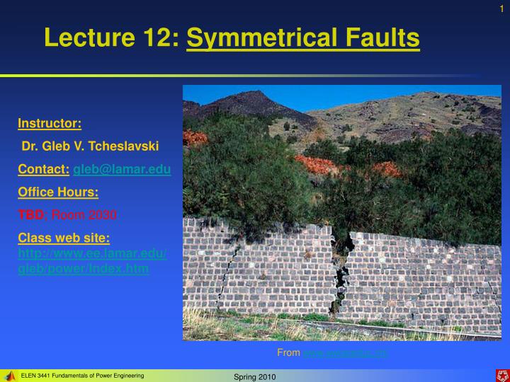
Lecture 12: Symmetrical Faults. Instructor: Dr. Gleb V. Tcheslavski Contact: gleb@lamar.edu Office Hours: TBD ; Room 2030 Class web site: http://www.ee.lamar.edu/gleb/power/Index.htm. From www.swisseduc.ch/. Preliminaries.

E N D
Lecture 12: Symmetrical Faults Instructor: Dr. Gleb V. Tcheslavski Contact:gleb@lamar.edu Office Hours: TBD; Room 2030 Class web site:http://www.ee.lamar.edu/gleb/power/Index.htm From www.swisseduc.ch/
Preliminaries A fault in a circuit is any failure that interferes with the normal flow of current to the load. In most faults, a current path forms between two or more phases, or between one or more phases and the neutral (ground). Since the impedance of a new path is usually low, an excessive current may flow. High-voltage transmission lines have strings of insulators supporting each phase. The insulators must be large enough to prevent flashover – a condition when the voltage difference between the line and the ground is large enough to ionize the air around insulators and thus provide a current path between a phase and a tower.
Preliminaries If flashover occurs on a single phase of the line, an arc will be produced. Such faults are called single line-to-ground faults. Since the short-circuit path has a low impedance, very high currents flow through the faulted line into the ground and back into the power system. Faults involving ionized current paths are also called transient faults. They usually clear if power is removed from the line for a short time and then restored. Single line-to-ground faults can also occur if one phase of the line breaks and comes into contact with the ground or if insulators break… This fault is called a permanent fault since it will remain after a quick power removing. Approximately 75% of all faults in power systems are either transient or permanent single line-to-ground faults.
Preliminaries Sometimes, all three phases of a transmission line are shorted together – symmetrical three-phase faults. Two phases of a line may touch, or flashover may occur between two phases – a line-to-line fault. When two lines touch each other and also touch the ground, the fault is called a double line-to-ground fault. Lighting strokes cause most faults on high-voltage transmission lines producing a very high transient that greatly exceeds the rated voltage of the line. This voltage usually causes flashover between the phase and the ground of the line creating an arc. Once the current starts flowing through the arc, it remains even after the lighting disappears.
Preliminaries High currents due to a fault must be detected by protective circuitry and the circuit breakers on the affected transmission line should automatically open for a brief period (about 1/3 second). This will allow ionized air to deionize. If the fault was transient, normal operation should be restored after reclosing the breaker. Therefore, many transient faults are cleared automatically. Otherwise, the circuit breaker should open again isolating the transmission line. Selecting an appropriate circuit breaker (type, size, etc.) is important…
Fault current transients in machines When a symmetrical 3-phase fault occurs at the terminals of a synchronous generator, the resulting current flow in the phases of the generator can appear as shown. The current can be represented as a transient DC component added on top of a symmetrical AC component. Therefore, while before the fault, only AC voltages and currents were present within the generator, immediately after the fault, both AC and DC currents are present.
Fault current transients in machines When the fault occurs, the AC component of current jumps to a very large value, but the total current cannot change instantly: series inductance of the machine will prevent this. The transient DC component of current is just large enough that the sum of the AC and DC components just after the fault equals the AC current just before the fault. Since the instantaneous values of current at the moment of the fault are different in each phase, the magnitude of DC components will be different in different phases. These DC components decay fairly quickly, but they initially average about 50 - 60% of the AC current flow the instant after the fault occurs. The total initial current is therefore typically 1.5 or 1.6 times the AC component alone.
Fault current transients in machines • Symmetrical AC component of the fault current: • Roughly 3 periods seen: • Subtransient: first cycle or so after the fault – AC current is very large and falls rapidly; • Transient: current falls at a slower rate; • Steady-state: current gets back to normal.
Fault current transients in machines It is possible to observe the three periods of fault current if the rms magnitude of the AC component current is plotted as a function of time on a semilogarithmic scale. It is possible to determine the time constants for the three periods…
Fault current transients in machines The AC current flowing in the generator during the subtransient period is called the subtransient current and is denoted by I”. This current is caused by the damper windings of synchronous machines. The time constant of the subtransient current is denoted by T” and it can be determined from the slope. This current may be 10 times the steady-state fault current. The AC current flowing in the generator during the transient period is called the transient current and is denoted by I’. It is caused by a transient DC component of current induced in the field circuit of a synchronous generator at the time of fault. This transient field current increases the internal generated voltage of a machine and, therefore, an increased fault current. The time constant of a field circuit T’ is much larger than the time constant of the damper winding, therefore, the transient period lasts longer than the subtransient. This current is often as much as 5 times the steady-state fault current.
Fault current transients in machines After the transient period, the fault current reaches a steady-state condition. the steady-state rms current is denoted by Issand is approximated by the fundamental frequency component of the internal generated voltage normalized by the synchronous reactance: (12.11.1) The rms magnitude of the AC fault current in a synchronous generator varies over time as (12.11.2)
Fault current transients in machines Usually, subtransient and transient reactances are defined for convenience. The subtransient reactance is the ratio of the fundamental component of the internal generated voltage to the subtransient component of current at the beginning of the fault: (12.12.1) Similarly, the transient reactance is the ratio of the fundamental component of the internal generated voltage to the transient component of current at the beginning of the fault. This value of current is found by extrapolating the transient region back to time zero (12.12.2)
Fault current transients in machines For the purposes of sizing protective equipment, the subtransient current is often assumed to be (12.13.1) and the transient current is (12.13.2) which are the maximum values of the respective currents. Note: we assume that all three phases are shorted simultaneously. If the fault does not affect all three phases equally, the analysis below is not applicable.
Fault transients in synchronousmotors When a short circuit develops in a system containing a synchronous motor, the motor starts acting as a generator converting its mechanical energy (stored in the inertia of its rotor) into electrical power, which is supplied to the power system. Since a synchronous motor is physically the same machine as a synchronous generator, it also has a subtransient reactance and transient reactance that must be considered in determining the total fault current in the power system.
Fault transients in inductionmotors An induction motor is an AC machine that has only damper windings on its rotor. Since damper windings are major source of current during the subtransient period, the induction motors in a power system should be considered during calculations of subtransient currents flowing in faults. Since currents in a damper winding are of little importance during the transient and steady-state periods of faults, induction motors may be ignored in fault current analysis after the subtransient period.
Fault current transients Example 12-1: A 100 MVA, 13.8 kV, Y-connected, 3 phase 60 Hz synchronous generator is operating at the rated voltage and no load when a 3 phase fault occurs at its terminals. Its reactances per unit to the machine’s own base are and the time constants are • The initial DC component in this machine averages 50 percent of the initial AC component. • What is the AC component of current in this generator the instant after the fault? • What is the total current (AC + DC) in the generator right after the fault occurs? • What will the AC component of the current be after 2 cycles? After 5 s?
Fault current transients The base current of the generator can be computed as The subtransient, transient, and steady-state currents are (per-unit and Amps)
Fault current transients • The initial AC component of current is I” = 34,900 A. • The total current (AC and DC) at the beginning of the fault is c) The AC component of current as a function of time is After 2 cycles t = 1/30 s and the total current is which has the largest contribution from the transient current component – transient period. At 5 s, the current reduces to which is in a steady-state period.
Fault current transients Example 12-2: Two generators are connected in parallel to the low-voltage side of a transformer. Generators G1 and G2 are each rated at 50 MVA, 13.8 kV, with a subtransient resistance of 0.2 pu. Transformer T1is rated at 100 MVA, 13.8/115 kV with a series reactance of 0.08 pu and negligible resistance. Assume that initially the voltage on the high side of the transformer is 120 kV, that the transformer is unloaded, and that there are no circulating currents between the generators. Calculate the subtransient fault current that will flow if a 3 phase fault occurs at the high-voltage side of transformer.
Fault current transients Let choose the per-unit base values for this power system to be 100 MVA and 115 kV at the high-voltage side and 13.8 kV at the low-voltage side of the transformer. The subtransient reactance of the two generators to the system base is Therefore: The reactance of the transformer is already given on the system base, it will not change
Fault current transients The per-unit voltage on the high-voltage side of the transformer is Since there is no load on the system, the voltage at the terminals of each generator, and the internal generated voltage of each generator must also be 1.044 pu. The per-phase per-unit equivalent circuit of the system is We observe that the phases of internal generated voltages are arbitrarily chosen as 00. The phase angles of both voltages must be the same since the generators were working in parallel.
Fault current transients To find the subtransient fault current, we need to solve for the voltage at the bus 1 of the system. To find this voltage, we must convert first the per-unit impedances to admittances, and the voltage sources to equivalent current sources. The Thevenin impedance of each generator is ZTh = j0.4, so the short-circuit current of each generator is The equivalent circuit
Fault current transients Then the node equation for voltage V1 Therefore, the subtransient current in the fault is Since the base current at the high-voltage side of the transformer is the subtransient fault current will be
Internal generated voltages of loaded machines under transient conditions The per-phase equivalent circuit of a synchronous generator is shown. The internal generated voltage is found from the Kirchhoff’s voltage law as (12.24.1) If the series resistance can be ignored, the internal generated voltage is (12.24.2) Therefore, the internal generated voltage within a synchronous generator will change with load on the machine. A similar equation exists relating the internal generated voltage and terminal voltage of a synchronous generator under subtransient conditions.
Internal generated voltages of loaded machines under transient conditions The per-phase equivalent circuit of a synchronous generator under subtransient conditions is shown. The internal generated voltage found from the Kirchhoff’s voltage law is (12.25.1) Therefore, the internal voltage EA” under subtransient conditions can be calculated if the load current and the terminal voltage are known just before the fault. The voltage determined by (12.25.1) is the voltage driving the subtransient fault current flow from the generator and is called sometimes the voltage behind subtransient reactance. Since this voltage varies as a function of the load on the generator before the fault occurs, the subtransient current flow in a fault will depend on the prefault load conditions of the power system. This variation is typically less than 10 % for different load conditions. The voltage behind subtransient reactance can be approximated as the prefault phase voltage of the generator.
Internal generated voltages of loaded machines under transient conditions The per-phase equivalent circuit of a synchronous generator under transient conditions is shown. The internal generated voltage found from the Kirchhoff’s voltage law is (12.26.1) Therefore, the internal voltage EA’ under transient conditions can be calculated if the load current and the terminal voltage are known just before the fault. The voltage determined by (12.25.1) is the voltage driving the transient fault current flow from the generator and is called sometimes the voltage behind transient reactance. Since this voltage varies as a function of the load on the generator before the fault occurs, the transient current flow in a fault will depend on the prefault load conditions of the power system. This variation is also typically less than 10 % for different load conditions. The voltage behind transient reactance can be approximated as the prefault phase voltage of the generator.
Internal generated voltages of synchronous motors Since synchronous motors are the same machines as synchronous generators, they have the same types of subtransient and transient reactances. When the motor is short-circuited, it does not receive power from the line but its field circuit is still energized and still spinning (due to inertia in the machine and in its load). Therefore, the motor acts as a generator, supplying power to the fault. The equivalent circuit of a synchronous motor is the same as the one of the synchronous generator except that the direction of the current flow is reversed. Therefore, the equations for the internal generated voltage, voltage behind the subtransient reactance, and voltage behind transient reactance become (12.27.1) (12.27.2) (12.27.3) These voltages can be used in subtransient and transient fault current analyses similarly to the analysis of synchronous generators.
Internal generated voltages of loaded machines under transient conditions Example 12-3: A 100 MVA, 13.8 kV, 0.9 PF lagging, Y-connected, 3 phase, 60 Hz synchronous generator is operating at rated voltage and full load when a symmetrical 3 phase fault occurs at its terminals. The reactances in per-unit to the machine’s own base are • If the generator operates at full load when the fault develops, what is the subtransient fault current produced by this generator? • If the generator operates at no load and rated voltage when the fault develops, what is the subtransient fault current produced by this generator? Observe that this calculation is equivalent to ignoring the effects of prefault load on fault currents. • How much difference does calculating the voltage behind subtransient reactance make in the fault current calculations?
Internal generated voltages of loaded machines under transient conditions The base current of the generator can be computed as • Before the fault, the generator was working at rated conditions and the per-unit current was: The voltage behind subtransient reactance is Therefore, the per-unit fault current when terminals are shorted is
Internal generated voltages of loaded machines under transient conditions b) Before the fault, the generator was assumed to be at no-load conditions and the per-unit current was: The voltage behind subtransient reactance is Therefore, the per-unit fault current when the terminals are shorted is c) The difference in fault current between these two cases is The difference in the fault current when the voltage behind subtransient reactance is considered and when it is ignored is small and usually systems are assumed unloaded.
Fault current calculations using the impedance matrix • So far, we were considering simple circuits. To determine the fault current in a system: • Create a per-phase per-unit equivalent circuit of the power system using either subtransient reactances (if subtransient currents are needed) or transient reactances (if transient currents are needed). • Add a short circuit between one node of the equivalent circuit and the neutral and calculate the current flow through that short by standard analysis. • This approach always works but can get complex while dealing with complex systems. Therefore, a nodal analysis technique will be used. • We introduce a new voltage source in the system to represent the effects of a fault at a bus. By solving for the currents introduced by this additional voltage source, we will find fault currents automatically…
Fault current calculations using the impedance matrix Let us consider a power system shown. Assuming that we need to find the subtransient fault current at some node in the system, we need to create a per-phase, per-unit equivalent circuit using subtransient reactances X”. Additionally, we assume that the system is initially unloaded, making the voltages behind subtransient reactances
Fault current calculations using the impedance matrix The resulting equivalent circuit is shown. Suppose that we need to determine the subtransient fault current at bus 2 when a symmetrical 3 phase fault occurs on that bus.
Fault current calculations using the impedance matrix Before the fault, the voltage on bus 2 was Vf. If we introduce a voltage source of value Vf between bus 2 and the neutral, nothing will change in the system. Since the system operates normally before the fault, there will be no current If” through that source.
Fault current calculations using the impedance matrix Assume that we create a short circuit on bus 2, which forces the voltage on bus 2 to 0. This is equivalent to inserting an additional voltage source of value -Vf in series with the existing voltage source. The later will make the total voltage at bus 2 become 0. With this additional voltage source, there will be a fault current If”, which is entirely due to the insertion of the new voltage source to the system. Therefore, we can use superposition to analyze the effects of the new voltage source on the system. The resulting current If” will be the current for the entire power system, since the other sources in the system produced a net zero current.
Fault current calculations using the impedance matrix If all voltage sources except –Vf” are set to zero and the impedances are converted to admittances, the power system appears as shown. For this system, we can construct the bus admittance matrix as discussed previously: The nodal equation describing this power system is (12.36.1)
Fault current calculations using the impedance matrix With all other voltage sources set to zero, the voltage at bus 2 is –Vf, and the current entering the bus 2 is –If”. Therefore, the nodal equation becomes (12.37.1) where V1, V3, and V4 are the changes in the voltages at those busses due to the current –If” injected at bus 2 by the fault. The solution to (12.37.1) is found as (12.37.2)
Fault current calculations using the impedance matrix Which, in the case considered, is (12.38.1) where Zbus = Ybus-1. Since only bus 2 has current injected at it, the system (12.38.1) reduces to (12.38.2)
Fault current calculations using the impedance matrix Therefore, the fault current at bus 2 is just the prefault voltage Vf at bus 2 divided by Z22, the driving point impedance at bus 2. (12.39.1) The voltage differences at each of the nodes due to the fault current can be calculated by substituting (12.39.1) into (12.38.2): (12.39.2)
Fault current calculations using the impedance matrix Assuming that the power system was running at no load conditions before the fault, it is easy to calculate the voltages at every bus during the fault. At no load, the voltage will be the same on every bus in the power system, so the voltage on every bus in the system is Vf. The change in voltage on every bus caused by the fault current –If” is specified by (12.39.2), so the total voltage during the fault is (12.40.1) Therefore, we can calculate the voltage at every bus in the power system during the fault from a knowledge of the pre-fault voltage at the faulted bus and the bus impedance matrix!
Fault current calculations using the impedance matrix • Once these bus voltages are known, we can calculate the fault current flowing in the transmission line using bus voltages and the bus admittance matrix. • The general procedure for finding the bus voltages and line currents during a symmetrical 3 phase fault is as follows: • Create a per-unit equivalent circuit of the power system. Include subtransient reactances of each synchronous and induction machine when looking for subtransient fault currents; include transient reactances of each synchronous machine when looking for transient fault currents. • Calculate the bus admittance matrix Ybus. Include the admittances of all transmission lines, transformers, etc. between busses including the admittances of the loads or generators themselves at each bus. • Calculate the bus impedance matrix Zbus as inverse of the bus admittance matrix. • Assume that the power system is at no load and determine the voltage at every bus, which will be the same for every bus and the same as the internal voltage of the generators in the system. This is the pre-fault voltage Vf.
Fault current calculations using the impedance matrix 5. Calculate the current at the faulted busi as (12.42.1) 6. Calculate the voltages at each bus during the fault. The voltage at bus j during a symmetrical 3 phase fault at the bus i is found as (12.42.2) 7. Calculate the currents in any desired transmission line during the fault. The current through a line between bus i and bus j is found as (12.42.3)
Fault current calculations using the impedance matrix • Example 12-4: The power system depicted in slide 32 is working at no load when a symmetrical 3 phase fault is developed on bus 2. • a) Calculate the per-unit subtransient fault current If” at bus 2. • b) Calculate the per-unit voltage at every bus in the system during the subtransient period. • c) Calculate the per-unit current I1 flowing in line 1 during the subtransient period of the fault. • Following the 7 steps discussed before, we write: • The per-phase per-unit equivalent circuit is shown in slide 33. • The bus admittance matrix was previously calculated as
Fault current calculations using the impedance matrix 3. The bus impedance matrix calculated using Matlab as the inverse of Ybus is 4. For the given power system, the no-load voltage at every bus is equal to the pre-fault voltage at the bus that is 5. The current at the faulted bus is computed as
Fault current calculations using the impedance matrix 6. The voltage at bus j during a symmetrical 3 phase fault at bus I can be found as 7. The current through the transmission line 1 is computed as That’s it!