Download
1 / 39
390 likes | 393 Vues
This article provides an overview of the Virgo experiment, including its detector design, construction steps, commissioning plan, and data analysis preparation. It also highlights the main results and future steps of the experiment.

E N D
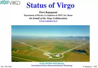
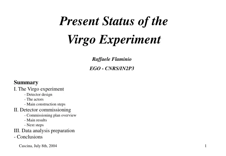
Present Status of the Virgo Experiment Raffaele Flaminio EGO - CNRS/IN2P3 • Summary • I. The Virgo experiment • - Detector design • - The actors • - Main construction steps • II. Detector commissioning • - Commissioning plan overview • - Main results • Next steps • III. Data analysis preparation • - Conclusions
Virgo: Laser • 20W, Nd:YVO4 laser, two pumping diodes • Injection locked to a 1W Nd:YAG master laser • Required power stability: 10-8 • Required frequency stability: mHz
Virgo: Input Mode-Cleaner Input mode-cleaner: curved mirror Input mode-cleaner: dihedron
Virgo: Mirrors • Material: fused silica • Dimension: 35 cm diameter, 10 cm thick • Mass: ~21 Kg • Surface deformation < l/100 • Anti-reflective coating ~ 10-4
Virgo: Suspensions • Multi stage pendulum • pre-isolator: inverted pendulum • cantilever springs for vertical isolation • cascade of six stages • height ~ 10 m • Expected attenuation > 1014 @ 10 Hz
Virgo: Output Optics • Light filtering with output mode-cleaner • 3.6 cm long monolithic cavity • Light detection with InGaAs photodiodes • 3 mm diameter, quantum efficiency > 90% Detection bench Output Mode-Cleaner
Virgo: Planned Sensitivity First attempt to extend detection band down to 10 Hz !
The Virgo collaboration • French-Italian collaborationsupported by CNRS in France and INFN in Italy • Composed by 11 laboratories: • About 170 people participated to the construction of Virgo • Main responsibilities: INFN Pisa Seismic isolation, Vacuum • INFN Florence/Urbino Seismic isolation • INFN Frascati Alignment • INFN Napoli Environmental monitoring, Alignment • INFN Perugia Mirror suspension • INFN Rome Mirror suspension and Control • LAPP Annecy DAQ, Detection, Vacuum chambers LAL Orsay Global control, Tube, Baffles OCA Nice Laser and Injection IPNL Lyon Mirror coatings • ESPCI Paris Mirror metrology LAPP Annecy, INFN Firenze, INFN Frascati, IPN Lyon, INFN Napoli, Observatoire de Nice, LAL Orsay, ESPCI Paris, INFN Perugia, INFN Pisa, INFN Roma
The construction of Virgo • Planning driven by the construction of the infrastructures • 1996 - 1998 Construction of central area • 1999 - 2002 Construction of the arms and the terminal buildings • Installation and commissioning of the central interferometer • 2001 - 2003 Vacuum tubes installation • 2002 - 2003 Installation of final mirrors and of terminal suspensions • 2003 - ….. Detector commissioning • ‘Central area’ • available since 1998
European Gravitational Observatory • What is EGO ? • Consortium settled up by the CNRS and the INFN • Main objectives of EGO ? • 1) to support the commissioning of Virgo, its operation, maintenance and upgrades • 2) to create and run a computing center for the analysis of data, • 3) to ensure the maintenance of the site and the related infrastructures • 4) to promote R&D useful for the detection of gravitational waves • Large support given to the commissioning activities: • Support to most of the main Virgo sub-systems • Leading role in: alignment, injection control, suspension control, data storage and vacuum • Interferometer operation
Commissioning plan overview • Phase A: Commissioning of interferometer arms • Phase B: Commissioning of the recombined interferometer • Phase C: Commissioning of the recycled interferometer • Status today: • - phase B near to completion • - moving to phase C
Commissioning plan overview • Phase A: Commissioning of interferometer arms • Phase B: Commissioning of the recombined interferometer • Phase C: Commissioning of the recycled interferometer • Status today: • - phase B near to completion • - moving to phase C
Commissioning plan overview • Phase A: Commissioning of interferometer arms • Phase B: Commissioning of the recombined interferometer • Phase C: Commissioning of the recycled interferometer • Status today: • - phase B near to completion • - moving to phase C
Commissioning plan overview • Phase A: Commissioning of interferometer arms • Phase B: Commissioning of the recombined interferometer • Phase C: Commissioning of the recycled interferometer • Status today: • - phase B near to completion • - moving to phase C
Power fluctuations due to: • - laser frequency noise (above few Hz) • - mirror angular motions (below few Hz) Cavities alignment & locking • As soon as injection and north arm suspensions became available (September 2003) • 1) Cavity alignment • 2) North cavity locking using B1’ • 3) Output mode-cleaner locking • 4) North cavity lock using B1
Laser frequency noise reduction • Laser frequency noise induced by input mode-cleaner control noise • Noise reduced when control gain/bandwidth reduced Peaks height might be a problem for recycling locking ..… work in progress
Automatic alignment: principle • Anderson technique: • - Modulation frequency coincident with cavity TEM01 mode • - Two quadrants looking at the cavity transmission (at two different Guoy phases) • - Four signals to control the 2x2 mirror angular positions (NI & NE)
Automatic alignment: results • Automatic alignment operated on both arms • - bandwidth ~ 3-4 Hz • - control precision ~ 0.1 mrad rms • It allows to: • - switch completely OFF local controls on all four cavity mirrors • stabilize power stored in the cavity • increase locking duration
Cavity transmission Cavity transmission Correction to the mirror Correction to the mirror Suspension point position Suspension point position 6 h 24 h ‘Tide control’ • Earth tide > Mirror actuators range ( ~ 100 mm) • Move low frequency component of the correction to the top of the inverted pendulum
Laser frequency stabilization • First test with North arm cavity • - North cavity error signal sent to the input mode-cleaner (below 200 Hz) and to the laser (above 200 Hz) • - Reference cavity error signal used to control cavity length at DC
C1 C2 C3 Commissioning runs: C1, C2 & C3 • Three commissioning runs performed since November ( ~ 1 each 2 months) • Each run last 3-4 days • Goals: • - Verify ITF cavities performances on longer time scales • - Provide real data to the collaboration • C1 (14-17/11/2003)- North cavity and OMC locked • C2 (20-23/02/2004) • - C1 + Automatic alignment • - West arm locked • C3 (23-27/04/2004) • - C2 + Laser frequency stabilization
Interferometer lock acquisition • Each cavity locked independently • Dark fringe locked with B2 or B1’ • Main outcome: • - B1’ signal very sensitive to alignment • - due to the use of Anderson technique • - effect disappear if B1 is used • - simulation work in progress to understand what will happen in the recycled interferometer First lock on Feb the 27th
Status of recombined interferometer today • Interferometer locked with B1 and B2 • Output mode-cleaner locked to the TEM00 mode • Automatic alignment on both arms • Tidal control on both arms • Laser frequency stabilized to cavities common mode • ITF common mode locked to reference cavity
C4 run: Summary • Configuration: recombined ITF with ‘nearly’ complete control system • Duration: 5 days, 24-29 June 2004 (last week) • Test periods at the beginning and at the end of the run • 9 losses of lock during quiet periods (all understood, one due to an earthquake in Alaska) • Longest locked period: ~ 28 h, relatively stable noise level
C4 run: ITF sensitivity ‘without power recycling’ C3 (April 2004) C4 (June 2004)
Next steps • Lock recycled interferometer • Planned strategy: based on the LIGO experience WE NE • Present status: • - State 2: locked • - State 3: locked for 10 min with WE mirror misaligned • Potential problem due to light backscattered inside the input mode-cleaner • Short term solution: reduce light entering the interferometer • Mid-term solution: add optical isolation between the interferometer and the input mode-cleaner • Next week: try to lock state 4
Data analysis organization • Six working groups settled up inside Virgo since 1998 • h Reconstruction: chair F.Marion (LAPP Annecy) • Noise analysis (data quality): chair J.Y.Vinet (OCA, Nice) • Coalescing binaries: chair A.Vicere (INFN Florence/Urbino) • Burst: chair P.Hello (LAL, Orsay) • Periodic sources: chair S.Frasca (INFN Rome) • Stochastic background: chair G.Cella (INFN Pisa) • Hardware and Software infrastructure developed for On-line/In-Time analysis: • h Reconstruction • Data quality • Coalescing binaries • Burst
h reconstruction Line Removal Whitening Trigger Manager Merlino Burst Merlino CB MBTA On-line/In-time analysis • Software architecture • All parts available • Each box runs properly in standalone mode • Connection between all boxes running • Full connection has to be tested under realistic conditions • Connection to DAQ foreseen in the next fall • Hardware architecture • 300 GFlops PC’s farm being deployed at EGO • Mainly needed for coalescing binaries search • Will be fully available next year
Mock Data Challenge • 3 MDC since the beginning of 2004 (January, March and June) • Common work between h Reconstruction, Coalescing binaries and Burst groups • Several configurations: • “Theoretical” Virgo noise • Noise spectral density as during Virgo run E4 • Noise as generated by a simulation of full Virgo in the current configuration • Include some non-stationarities (power modulations) and non-linearities (ARCH models) • Losses of lock • Main purpose: test the full In-Time chain
‘Real Data Challenge’ • Data analysis people re-starting use of real data (it had been done in the past using CITF data) • Injection of fake signals (burst and coalescing binaries) during C3 and C4 • Made acting on mirrors using the coils • Will be done with an independent optical calibrator as soon as sensitivity allows it • Bring Data Analysis people closer to the real data
Off-line analysis • Use of national computing centers: • - CC/In2p3 in Lyon • - CNAF in Bologna • So far mainly used to test algorithm for periodic sources search • Roma, Bologna, Napoli (about 30 machines) within INFN-Grid • Lyon (25 processors) as a classic batch system
Collaborative data analysis • LIGO-Virgo MoU proposal • “Topic driven” collaboration, focused initially on a two well defined subjects (inspirals+bursts) • Real analysis will start when a comparable sensitivity will be reached • In the meantime: • open meetings between the people involved • joint working groups will write a white paper • Responsibles for the joint working groups (Virgo side): • A. Vicere, B. Mours (inspirals) • P. Hello, L. Brocco (bursts) • The activity is coordinated by the data analysis coordinator. • Full ability of anyone in the collaboration to participate in any analysis, accordingly with the internal rules of each experiment. • Meeting at Cascina two weeks ago • Need to start an effort at an European level • Hope WG2 of ILIAS-GWA will help
Conclusions • Construction of Virgo completed • - Last suspension assembly completed in November 2003 • Detector commissioning started in October 2003 • - Commissioning of the 3 km arms completed • - Recombined interferometer control 95% completed (noise identification starting) • - Commissioning of recycled interferometer starting • Data analysis preparation progressing • Hope to have first scientific run in 2005
IMC- ITF spurious fringes backscattering Input laser beam ITF reflected beam • Backscattering on mode-cleaner mirror • fringes at ITF input • spurious signals in mode-cleaner control • input mode-cleaner lock losses • Consequences: • need to misalign recycling mirror • reduction of recycling gain • lock acquisition longer • smaller duty cycle fringes • Possible solutions: 1) use of Faraday isolator • 2) better mode-cleaner mirror • Solution 2) adopted so far