Download
1 / 21
260 likes | 587 Vues
Architectural Drawings. Residential Construction Unit 1 Mr. Todzia. A rchitectural Drawing. An architectural drawing or is a technical drawing of a building project that falls within the definition of architecture.

E N D
ArchitecturalDrawings Residential Construction Unit 1 Mr. Todzia
Architectural Drawing • An architectural drawing or is a technical drawing of a building project that falls within the definition of architecture. • Technical Drawing- is a plan that visually communicates how something functions or is to be constructed. • Architecture- The art and science of design and the erecting of buildings and other physical structures.
Arch. Drawings Continued Architectural drawings are used by architects and others for a number of purposes: • to develop a design idea into a coherent proposal • to communicate ideas and concepts • to convince clients of the merits of a design • to enable a building contractor to construct it • as a record of the completed work • to make a record of a building that already exists
Arch. Drawings Continued • Architectural drawings are drawn according to a set of conventions, which include particular views (floor plan, elevations, section etc.), sheet sizes, units of measurement and scales, annotations and cross referencing. • conventionis a set of agreed, or generally accepted standards, often taking the form of a custom.
History of Arch Drawings • Historically, drawings were made in ink on paper or a similar material, and any copies had to be laboriously made by hand. • The twentieth century saw a shift to drawing on tracing paper, so that mechanical copies could be run off efficiently.
Evolution of Arch. Drawings • The development of the computer had a major impact on the methods used to design and create technical drawings making manual drafting almost obsolete, and opening up new possibilities of form using organic shapes and complex geometry. • Today the vast majority of drawings are created using CAD software
C.A.D. • Computer-aided design (CAD), is the use of computer technology for the process of design and design-documentation. Designing in CAD allows for two things to take place easier than the older methods? Making copiesand changes
Standard Views used in architectural drawing • A floor plan is the most fundamental architectural diagram, a view from above showing the arrangement of spaces in a building in the same way as a map, but showing the arrangement at a particular level of a building.
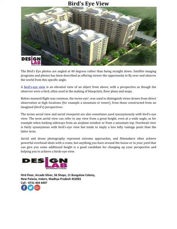
Elevation View • An elevation is a view of a building seen from one side, a flat representation of one façade. • This is the most common view used to describe the external appearance of a building. • Each elevation is labeled in relation to the compass direction it faces, e.g. the north elevation of a building is the side that most closely faces north
Cross Section View • A cross section represents a vertical plane cut through the object, in the same way as a floor plan is a horizontal section viewed from the top. • In the section view, everything cut by the section plane is shown as a bold line, often with a solid fill to show objects that are cut through, and anything seen beyond generally shown in a thinner line. • Sections are used to describe the relationship between different levels of a building.
Site Plan • A site plan is a specific type of plan, showing the whole context of a building or group of buildings. • A site plan shows property boundaries and means of access to the site, and nearby structures if they are relevant to the design.
Scaled Drawings • Architectural drawings are drawn to scale, so that relative sizes are correctly represented. • The scale is chosen both to ensure the whole building will fit on the chosen sheet size, and to show the required amount of detail. • For example a drawing could be done in ¼ inch scale. This means that if you measured ¼ inch on the drawing, it would represent 1 ft in real life.
Architectural Symbols • All drawings use a common set of symbols, similar to a language. See Architectural Symbols hand out.
Annotations • Working drawings include dimensions. • They specify: • room size • wall lengths • door and window locations
Detail Views • Detail drawings show a small part of the construction at a larger scale, to show how the component parts fit together. • They are also used to show small surface details, for example decorative elements. • See handout of house plans
Schedules • Window, door or trim scheduleis a detailed list of: • window types • Window sizes • installation details • finishing instructions (painted, stained, vynal, prefinished) • See house plans for examples