Download
1 / 19
200 likes | 526 Vues
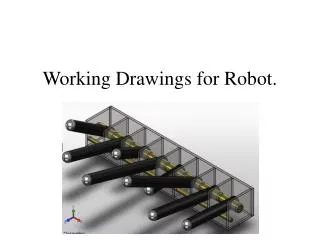
Working Drawings. Unit 10. Working Drawings. Two basic types: Detail drawings of the parts produced Assembly drawings for each unit or sub-unit to be put together Convey engineering and design requirements to produce the finished part. Working Drawing Information. Order material

E N D
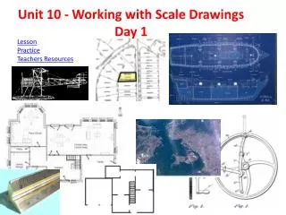
Working Drawings Unit 10
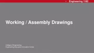
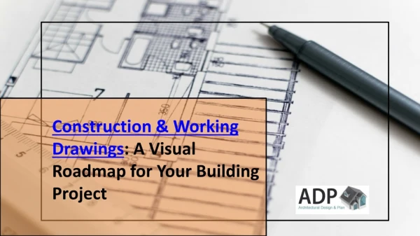
Working Drawings • Two basic types: • Detail drawings of the parts produced • Assembly drawings for each unit or sub-unit to be put together • Convey engineering and design requirements to produce the finished part.
Working Drawing Information • Order material • Plan manufacturing operations, tooling, and manufacturing facilities • Process material • Inspect and control product quality and reliability • assemble • test and model • package, box, and ship • determine cost • catalog • install and service • conduct final acceptance test • make alterations • record for duplication, repair, or replacement
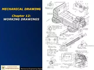
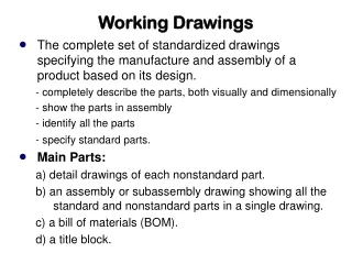
Detail Drawings • Drawings made for a single part. • Provide all the information to produce that part. • Supplies the worker with the following information. • Name of the part. • Shape description of the part • Dimensional size of the part and the part’s features. • Notes detailing materials, special machining, finish, heat-treatment, etc..
Detailing • Pull separate parts from the assembly and draw them individually • After Assembly Drawings • Details include appropriate views and dimensions • Standard items that can be purchased off the shelf are shown on the assembly drawing and listed in the parts list - no separate details required.
Assembly Drawing • Show the working relationship of the various parts of a machine or structure as they fit together. • Supplies the worker with the following information. • Name of the assembly mechanism or subassembly. • Visual relationship of one part to another in order to correctly assemble the various parts • List of parts • Bill of materials may be included. • Overall size and location dim. When necessary to check clearance fitting.
Selection of Assembly Drawings • Factors of View selection: • Depict the assembly in its natural position in space. • Defines clearly how the parts fit together. • Describes the functional relationship of the parts. • Minimum number of views needed to define the assembly should be used (often only one view is needed).
Assembly Drawing Types • Prepared for each group of items that is to be joined together to form an assembly. • May be on same sheet as details or separate sheet. • Assembly is usually sheet number one. • Includes graphic layout (pictorial drawing), necessary notes, and a list or bill of materials. • Notes call out subsequent operations to be performed on the assembly.
Sub-assembly • Variation of an assembly drawing. • Include a related group of parts
Working Assembly • Fully dimensioned drawings • Combine the features of detail drawings with assembly drawings
Provide necessary information to install or erect a piece of equipment. Installation Assembly
Hidden, Crosshatching, and Phantom Lines on Assembly Drawings • Hidden lines not shown. • Instead, use section views to describe internal parts. • Material symbols (including crosshatching is optional). • Showing a part before an assembly by using phantom lines and after the assembly operation by using object lines is also acceptable.
Part Identification on an Assembly • The parts list is keyed to the assembly by ballooning the individual pieces of the unit. • Leader lines from balloons should not cross. • Balloon circles can be drawn between .5 and .75 inches in diameter.
Parts List • The assembly drawing must have a complete parts list. • Each parts list includes: • individual part numbers • name and description of each part • material and quantity of all items required for one complete assembly • Placed above the title block • Heading “Parts List” is placed on the bottom of the list and the part number read upward.
Revision of Engineering Drawings • Revision block used to record changes to the drawing. • Extremely important link in engineering documentation - changes have far reaching effects within organization. • Terminology used in revision blocks include: added, approval, change, deleted, obsolete, redrawn, revision, revision designation.