Download
1 / 45
480 likes | 874 Vues
Working Drawings Overview Production or working drawings are specialized engineering drawings that provide the information required to make the part or assembly of the final design.

E N D
Overview • Production or working drawings are specialized engineering drawings that provide the information required to make the part or assembly of the final design. • Working drawings are the complete set of standardized drawings specifying the manufacture and assembly of a product based on its design.
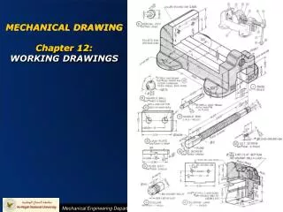
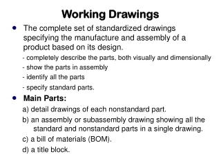
Working Drawings • Working drawings of an assembly include: • Detail drawings of each nonstandard part • An assembly or subassembly drawing showing all the standard and nonstandard parts in a single drawing • A bill of materials (BOM) • A title block
Detail Drawings • A detail drawing is a dimensioned, multiview drawing of a single part, describing the part’s shape, size, material, and finish in sufficient detail for the part to be manufactured based on the drawing alone.
Detailed Drawings • Adhere to ANSI and company standards • Lettering • Dimensioning • Part numbers • Notes • Tolerances
Standard Parts • Standard parts such as threaded fasteners, bushings, and bearings are NOT drawn as details since they are normally purchased • Standard parts ARE shown in the assembly drawing
Assembly Drawings • An assembly drawing shows how each part of the design is put together. • Very large assemblies may be broken into subassemblies.
Assembly Drawings • Assembly drawings normally consist of the following • All parts, drawn in operating position • A parts list or bill of materials • Detail callout • Machining and assembly operations and critical dimensions related to these functions
Assembly Drawings • Assembly drawings are used to describe how parts are put together. • The views chosen should describe the relationships of the parts • The number of views chosen should be the minimum necessary to describe the assembly
Assembly Drawings • Dimensions are not shown on assembly drawings, unless necessary to provide overall assembly dimensions, or to assist machining operations necessary for assembly • Hidden lines are omitted in assembly drawings, except when needed for assembly or clarity
Assembly Drawings • 3 basic types of assembly drawings • Outline assembly • Sectioned assembly • Pictorial assembly
Outline Assembly • Gives general graphic description of the exterior shape • Typically used for parts catalogs and installation manuals for simple assemblies • Omit hidden lines, except for clarity
Sectioned Assembly • Gives a general graphic description of the interior shape by passing a cutting plane through all or part of the assembly. • Typically, show multiple views with one view in full section.
Sectioned Assemblies • Important conventions to follow: • Standard parts (fasteners, bearings, etc.) are not sectioned, but drawn with all exterior features • Adjacent parts in sectioned are crosshatched at different angles and/or different hatch patterns • Thin parts, such as gaskets, are shown solid black
Pictorial Assembly • Gives a general graphic description of each part, and uses center lines to show how the parts are assembled • Normally drawn in isometric view with hidden lines removed or rendered • Typically used in maintenance manuals
Exploded Views in Unigraphics • Exploded Views Toolbar
Create the explosion in your assembly Create the explosion Edit the location of each part You can view it exploded or not
Exploded Views in Unigraphics • Creating an explosion does NOT move the parts • It suppresses the constraints • You will need to move the parts itself using the edit explosion tool • The auto-explode components tool may also be used on simple assemblies
Select which parts to move • Move the part • X,Y, or Z-translation (click on the axis and drag) • X,Y, or Z-Rotation (click on the round dot and drag) Manipulate the coordinate system without moving the part
Place a view of the exploded assembly on a drafting sheet (IT HAS TO BE A TFR-TRI VIEW TO SHOW THE EXPLOSION)
Part Numbers • Every part in an assembly is assigned a part number • Part number is typically alphanumeric • Used to track part within the company • Leader line with balloon assigns a detail number to each part • Sequential number • Referenced in bill of materials or notes
Bill of Materials • Also referred to as parts list • Normally shows the following for each part: • Detail number • Quantity needed for assembly • Description or name of part • Catalog number (for standard parts) • Part number (for company parts)
Title Blocks • Used to record important information necessary for working drawings • Normally located in the lower right corner of the drawing sheet • Both ANSI standard and company specific title blocks are common
Title Blocks • Typically include the following information: • Name/address of company • Title of drawing • Drawing number • Approval names and dates • Scale • Sheet number
Revision Block • Used to track changes in design • Normally located in upper right corner of drawing
Tolerance Specifications • For those dimensions that are not specifically toleranced, a general tolerance note is used • Typically placed in the lower right corner, near the title block