Fetch & Execute Example: MPY R1, x000040
40 likes | 182 Vues
Learn how to execute a multiply operation in this step-by-step example, with instruction processing phases including fetch, decode, and execute.

Fetch & Execute Example: MPY R1, x000040
E N D
Presentation Transcript
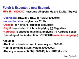
Fetch & Execute: a new Example • MPY R1, x000040 (assume all operands are 32bits, 4bytes) • Definition: REG[1] = REG[1] * MEM[x000040] • Instruction size: is given as 32bits • Opcode: is 4 bits, ‘5’ encodes a multiply • Reg #: is encoded in 4 bits, implying ?? Registers • Address: is encoded in 24bits, implying ?? Address space • Encoding of the instruction: x51000040 (machine language)Assume: • The Instruction is stored in memory at x000100 • Reg[1] contains a 32bit value: x00000003 • The 4byte value at MEM[x000040] is xffffffff (I.e. -1)
Instruction Processing: FETCH PHASE • Given PC=x000100, then the FETCH will • proceed in approximately this order: • ADDRESS BUS = x000100 • MAR = x000100 • CONTROL BUS = Chip Select (CS), Read, Size=4 bytes • (wait for memory access time: 100 clock cyc) • MDR = x51000040 = MEM[MAR] • DATA BUS = x51000040 • IR = x51000040 • PC = x000104 • SUMMARY: 1 memory access to read(fetch) the • instruction (in the fetch phase of instr. cycle) F D EA OP EX S
Instruction Processing: DECODE • First identify the opcode. • In our example, this is the first four bits of instruction. • A 4-to-16 decoder asserts a control line correspondingto the desired opcode. • MPY control line is asserted F D EA OP EX S
EXECUTE PHASE: • READ both operands’ data, MPY, store result: • ADDRESS BUS = x000040 • MAR = x000040 • CONTROL BUS = Chip Select (CS), Read, Size=4 bytes • (wait for memory access time: 100 clock cycles) • MDR = xff ff ff ff = MEM[MAR] • DATA BUS = xff ff ff ff • ALU INPUTS:xff ff ff ff, and x00000003 (from REG[x1]) • ALU SELECTOR = “multiply” • ALU OUTPUT: xff ff ff fd • REG[x1] = xff ff ff fd • SUMMARY: 1 memory access to read(fetch) a • data operand (in the execute phase of Instr. Cycle) F D EA OP EX S