Download
1 / 27
270 likes | 277 Vues
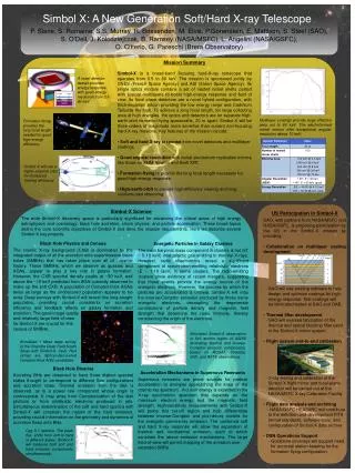
Bologna, 16.03.2006. Simbol-X INAF-PRIN KOM. Thermal Blankets A. Collura. XACT facility at INAF-OAPA. Facility for the development, test and calibration of instrumentation for soft X-ray Astronomy.

E N D
Bologna, 16.03.2006 Simbol-X INAF-PRIN KOM Thermal Blankets A. Collura
XACT facility at INAF-OAPA • Facility for the development, test and calibration of instrumentation for soft X-ray Astronomy. • Transmissivity, reflectivity, and quantum efficiency measurements in the soft X-ray band (0.1-20 keV) and UV. • Test and calibration in full imaging mode of moderate angular resolution (PSF > 10” FWHM), and small diameter (< 40 cm) grazing incidence X-ray optics. • Test and calibration of X-ray cryogenic detectors. [Collura et al. 1994(8), 1996(14); Barbera et al., 1994(7), Barbera et al. 2000(62)]
18 m 34.5 m The X-Ray Beam-Line Present configuration 100 63 55 40 50 35 25 30 25 30 20 Ø 20 50 100 100 100 100 100 L 100 200 200 200 200 200 100 New Configuration 200 80 100 80 80 80 80 63 63 55 50 40 30 30 35 20 25 25 Ø L 50 100 100 200 200 200 100 100 200 100 200 100 100 250 250 250 250 80 350
Sources, Detectors and Monochromators ,SSD SSD = Solid State Detector
Participation in the development and calibration of experiments for soft X-ray Astronomy • Chandra HRC: development and calibration of the UV/Ion shields, X-ray quantum efficiency of microchannel plates, end to end test; • Newton-XMM EPIC: development and calibration of the thin and medium filters, monitoring ageing effects of back-up filters; • JET-X CCD: development and calibration of the filters; • Solar-B XRT: development and calibration of the filters, reflectivity measurements of flat mirror samples.
Chandra HRC: development of the UV/Ion shields • Investigation of different plastic materials • Simulation of the expected out of band rejection • Vibrational and acoustic tests • Baseline design • Calibration plan
Chandra HRC: UV transmission measurements of the UV/Ion shields at the XACT facility Aluminum oxidation and interferences New filter design: Polyimide instead of Lexan, and single layer of aluminum (impact on Chandra ACIS, Newton-XMM EPIC, and JET-X).
Chandra HRC: X-ray transmission measurements of the UV/Ion shields at the XACT facility • X-ray Source • Transmis. Grating Monoch. • GFPC + MCP detectors
Chandra HRC: X-ray transmission measurements of the UV/Ion shields at Bessy Synchrotron • X-ray Transmission modeling • XANES and EXAFS
Chandra HRC: Measurement of the UV/Visible refractive index of Polyimide • UV/Visible transmission measurements • of monolayer films • Parametric model of the extinction • coefficient K
Newton-XMM EPIC: Filter development and calibration plan Newton-XMM EPIC: UV filter transmission measurements • Out of band rejection Newton-XMM EPIC: Synchrotron X-ray filter transmission measurements • X-ray Transmission modeling • XANES and EXAFS
Newton-XMM EPIC: X-ray shadowgraphs of thin and medium filters at the XACT facility • GFPC+MCP detectors • Mosaic of 9 images
Newton-XMM EPIC: Monitoring ageing effects of the thin and medium filters July 1997 July 2002 • Not modeled as an increase of aluminum oxidation • Possible explanations: Polyimide, Al surface roughness • No significant impact on the EPIC calibration
SOLAR-B XRT: Focal Plane Filter calibration • X_ray shadowgraphs • X-ray transmission measurements and modeling SOLAR-B XRT: Entrance Filters calibration • X-ray transmission measurements and modeling of • small filter samples SOLAR-B XRT: telescope calibration • Reflectivity measurements of flat mirror samples vs. • energy and angle of incidence. [Ongoing calibration program]
Simbol-X: Coperte Termiche • Studio dei requirements termici (Alcatel Alenia) • Baseline design (ottico - meccanico) (OAPA+Luxel+Alcatel Alenia) • Misure su witness samples (OAPA) • Design finale (OAPA+Luxel+Alcatel Alenia) • Realizzazione (Alcatel Alenia + Luxel (?)) • Test meccanici (Alcatel Alenia) • Calibrazione (OAPA) • Protoni lenti (resistenza + stopping pwr) TBD
Development of grazing incidence X-ray Optics • Plastic foils from common industrial applications • High surface smoothness by a combination of stretching • and rolling in higly polished rollers • Plastic is very light, elastic, cheap, has strong affinity to • coating • Plastic foils replicate the figure of the mandrel but not • the smoothness. Expensive superpolished mandrels not • required
Shaping and coating the foils • Single and multilayer coating on large size foils before shaping • Vacuum hold-down mandrels to form cylindrical or conical shells [Schnopper et al.,1999(30)]
Holding the foils • Foils hold inside grooves of the supporting wheels • Epoxy cured while foils are still inside the mandrel [Schnopper et al., 2001(42)]
Full X-ray imaging tests at XACT [Barbera et al., 2001(64)]
FWHM ~ 10” HPD ~ 2’ [Schnopper et al., 2002, Proc. SPIE 4851, in press]
Detector Source Simbol-X: Un’idea per il test delle ottiche • Realizzazione di 2 ottiche identiche • Montaggio sullo stesso asse con i fuochi in direzioni opposte • Sorgente X puntiforme in un fuoco, rivelatore nell’altro fuoco • La PSF misurata è in prima approssimazione la somma in quadratura delle due PSF • Possibilità di migliorare ulteriormente l’informazione con scambi, rotazioni, masking