Download
1 / 23
230 likes | 330 Vues
CEBAF Polarized Electron Source: Outlook & Horizon. Operations Group Meeting May 13 th & 20 th , 2009 Joe Grames. M. Poelker , P. Adderley , J. Clark , J. Grames , J. Hansknecht , M. Stutzman , R. Suleiman Graduate Students : J. Dumas, J. McCarter, K. Surles -Law.

E N D
CEBAF Polarized Electron Source: Outlook & Horizon Operations Group Meeting May 13th & 20th, 2009 Joe Grames • M. Poelker, P.Adderley, J. Clark,J. Grames, • J. Hansknecht, M.Stutzman, R. Suleiman • Graduate Students: J. Dumas, J. McCarter, K. Surles-Law
Following the summer SAD we begin a series of experiments with very demanding requirements of the polarized source (and of the accelerator too!) These so-called “parity violation” experiments aim to measure tiny physics dependent asymmetries in the scattering of polarized electrons from their targets. 500,001 1,000,000 499,999 Asymmetry = D / S = (500,001 – 499,999) / (1,000,000) = 2 ppm
Polarization Experiments The common technique you’ll find for learning the spin physics interaction is to reverse the sign of the beam (or target) polarization and measure the relative difference in detected signal: (R+ - R-) Aexp = = Aphysics • Pbeam • Ptarget (R+ + R-) Flip one or other… • For most experiments the z-component is important. This explains why: • Experiments need longitudinal beam polarization. • The word helicity is used (spin parallel/anti-parallel momentum).
The Imperfect World So, if R+ or R- changes because of anything other than the spin physics of the interaction, it is a false asymmetry. This results in the seemingly unattainable, golden rule for parity experiments: No beam property other than the beam polarization should change when the beam polarization reverses sign. • But, beam properties do change: • Intensity (first order) • Position (second order) • Energy (second order) • These come in different ways: • Laser light • Photocathode • Accelerator These happen before the electrons are even a beam…
Accelerator • A HC position difference on ANY aperture results in a HC intensity asymmetry. (Note we use absolute difference for position and relative asymmetry for intensity). • Apertures (Profile & Position): • Emittance/Spatial Filters (A1-A4) • Temporal Filter (RF chopping apertures) • Beam scraping monitors. • Any piece of beampipe! • The small apertures and tight spots (separation?) Adiabatic damping of the beam emittance may gain factors of 10-20 because of the reduction in amplitude of the beam envelope. Poor optics can reduce this gain by 10x. Poor optics stability can vary response between source and user.
Benchmarking PARMELA Simulation Results Against Beam-Based Measurements at CEBAF/Jefferson Lab – work of AshwiniJayaprakash, JLab Measurements at CEBAF/JLab PARMELA Simulation Results Similar Trends Message: Beam quality, including transmission, improves at higher gun voltage
CEBAF LLGun Features Load-Lock Gun at CEBAF since July 2007 • Multiple pucks (8 hours to heat/activate new sample) • Suitcase to add new photocathodes (one day to replace all pucks) • Mask to limit active area, no more anodizing • Vacuum features; NEG coated, smaller surface area, vacuum fired for low out-gassing rate, HV chamber never vented
Lifetime with Large/Small Laser Spots 2 1500 Expectation: ≈ 18 350 Tough to measure >1000 C lifetimes with 100-200 C runs! 5 15 This result frequently cited in support of plans for eRHIC at >25mA “Further Measurements of Photocathode Operational Lifetime at Beam Current > 1mA using an Improved 100 kV DC High VoltageGaAs Photogun,” J. Grames, et al., Proceedings Polarized Electron Source Workshop, SPIN06, Tokyo, Japan
1mA at High Polarization* * Note: did not actually measure polarization High Initial QE # prediction with 10W laser Vacuum signals Laser Power Beam Current
However, we never achieved good lifetime in tunnel… Ultimately, we believe this is a consequence of field emission.
We believed we had identified a leading suspect… …modified a HV chamber, commissioned at Test Cave, and installed this past SAD…
Field Emission – Most Important Issue Stainless Steel and Diamond-Paste Polishing Good to ~ 5MV/m and 100kV. 5MV/m • Flat electrodes and small gaps not very useful • Want to keep gun dimensions about the same – suggests our 200kV gun needs “quiet” electrodes to 10MV/m 100kV Work of Ken Surles-Law, Jefferson Lab
Let’s return to the Higher Voltage Gun… • Helps achieve ALL goals…. • More UP time at CEBAF, better beam quality for Parity Violation experiments • Longer lifetime at high average current (good for FEL and positron source) • Emittance preservation at high bunch charge and peak current • High Voltage Issues: • Field emission • Electrode design: reducing gradient and good beam optics • Hardware limitations at CEBAF (Capture, chopper) • Improve Vacuum • Ion pumps • NEG pumps • Outgassing • Gauges
“Inverted” Gun • Present Ceramic • Exposed to field emission • Large area • Expensive (~$50k) Medical x-ray technology e- • New Ceramic • Compact • ~$5k neg modules New design Want to move away from “conventional” insulator used on allGaAsphotoguns today – expensive, months to build, prone to damage from field emission.
Single Crystal Niobium: • Capable of operation at higher voltage and gradient • Buffer chemical polish (BCP) much easier than diamond-paste-polish Conventional geometry: cathode electrode mounted on metal support structure Replace conventional ceramic insulator with “Inverted” insulator: no SF6 and no HV breakdown outside chamber Work of Ken Surles-Law, Jefferson Lab Thanks to P. Kneisel, L. Turlington, G. Myneni
The horizon is … NOW • So, our gun plans are… • repair, test the original LL GUN (back in the Test Cave) • build a new inverted style gun (working beginning in EEL/Test Cave) • continue HV modeling gun for acceptable gradient/geometry • preparing new SS and Niobium electrodes for inverted gun • install new 150kV PS • Our plans are to install and operate higher voltage inverted gun, using existing preparation chamber, this summer. …and if that’s not enough…. The PREX experiment requires the ability to flip the electron polarization 180 degrees. Our plan is to do this with a new, second Wien filter & spin rotation solenoid magnet….
Summer ‘09 SAD Same good photocathode PREP and LOAD chambers • Spin Flipper: Stage 1 • Remove unbaked girder region between valve & chopper • Install new “normal” Wien for Physics program, with quad correction • Thoroughly test & transfer functionality for setting pol. • No need to move laser room. Install “Inverted” HV chamber with capabilities for higher voltage, anticipating better transmission & photocathode lifetime Preserve baked region, continue R&D/BS during Fall H-Wien + Quads Harp/A2 “match point”
Winter ‘10 SAD Same good photocathode PREP and LOAD chambers • Spin Flipper: Stage 2 • Replace baked region with spin flipper (vertical Wien filter + solenoid(s). • May be tilted pole Wien designed specifically for 90 deg operation at given known gun voltage Same Wien filter to set longitudinal polarization for Physics Same “Inverted” Gun, tested at higher voltage Spin Flip V-Wien Spin Flip Solenoid H-Wien + Quads Harp “match point” Harp/A2 “match point”
The End (unless you want a few more slides…)
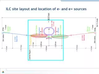
PhD Thesis: Polarized Positrons for JLab, Jonathan DUMAS Advisors: Eric Voutier, LPSC and Joe Grames, JLab Conventional un-polarized e+ Scheme (bremsstrahlung photon) ILC Polarized e+ Schemes/Demos (synchrotron/Compton polarized photon) OR • E = 50 GeV L = 1m E-166 Experiment High Polarization, High Current e- Gun (polarizedbremsstrahlung photon) T. Omori, Spin 2006 • Positron Yield scales with Beam Power • Replace GeV-pulsed with MeV-CW • Reduce radiation budget • Remain below photo-neutron threshold • Bunch/Capture to SRF linac • Compact source vs. Damping Ring • Unique capabilities • First CW source with helicity reversal
Proof of Principle Experiment: extendible to higher energy (& yield) Precision Electron Mott Polarimeter (~1%) • CEBAF Electron Source • High-P (~85%), High-QE (~3mA/500 mW) • e- bunch: 3mA @ 1497MHz demonstrated • Thesis: duty factor => low power, high peak • MeV-Accelerator • Cryounit tested to ~8 MeV • G0 setup 1.9mA @ 1497 MHz e- g e+ e- Precision Electron Spectrometer (~3%) Conversion Target (Tilted/Normal Tungsten Foils) G4 Beamline simulation e- after target not shown Spec. Dipole#1 g Brem Pair e+ e- DE = ±250 keV, DF = 2π Geant4 simulation DQ = ±20 Collimators Sweep Dipole g DQ = ±10 Geant4 simulation Spec. Dipole#2 DQ = ±5 Analyzer magnet g converter e+ Spectrometer (or e- & no spin rotation) Transmission Polarimeter (MIT loan)
The Source Group hosted two recent workshops: PESP2008 – Workshop on Polarized Electron Sources and Polarimeters JPOS09 – International Workshop on Positrons at JLab.