Download
1 / 24
330 likes | 541 Vues
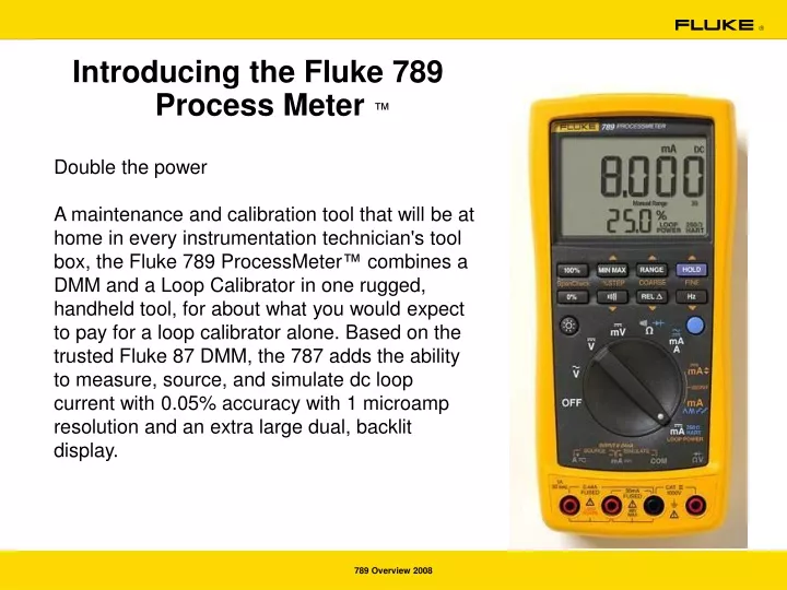
Introducing the Fluke 789 Process Meter ™. Double the power

E N D
Introducing the Fluke 789 Process Meter ™ Double the power A maintenance and calibration tool that will be at home in every instrumentation technician's tool box, the Fluke 789 ProcessMeter™ combines a DMM and a Loop Calibrator in one rugged, handheld tool, for about what you would expect to pay for a loop calibrator alone. Based on the trusted Fluke 87 DMM, the 787 adds the ability to measure, source, and simulate dc loop current with 0.05% accuracy with 1 microamp resolution and an extra large dual, backlit display.
Fluke 789 Getting Acquainted Feature Set • DMM 1000V Cat III Safety rating • Precision 1000V, 440 mA True-RMS digital multimeter • Frequency measurement to 20 kHz • Min/Max/Average/Hold/Relative modes • Diode Test and Continuity Beeper • Simultaneous mA and % of scale readout • 20mA dc current source / loop calibrator / simulator • Manual Step (100%, 25%, Course, Fine) plus Auto Step and Auto Ramp
Fluke 789 Getting Acquainted Feature Set • 24 V Loop Power Supply • Hart mode setting with loop power (adds 250 ohm resistor) • 100% larger dual display • 1200 ohm drive capability on mA source • Backlight with two brightness settings • 0-100% mA Span Check buttons to toggle between 4 and 20 mA • Infrared I/O serial port compatible with FlukeView Forms Software version 2. • Externally accessible fuses for easy replacement • Externally accessible battery for easy battery changes
Fluke 789 Features MAX – displays the maximum-recorded value MIN - displays the minimum-recorded value AVG –displays the average value since starting recording (up to 40 hours continuous recording time) Communication Port Extra large display The meter normally is in autorange mode meaning that the meter automatically selects the lowest range that will measure the applied input signal with the best resolution. (Auto Range showing on the display). Hold and AutoHold Relative reading feature to set the present measurement as a relative zero Frequency is the number of cycles a signal completes each second. To measure frequency, connect the meter to the signal source; then press Hz. Toggles the backlight low high and off for better illumination of the display CAT III 1000 V overvoltage protection Broad range of measurement functions, including Resistance and continuity
Getting Acquainted with the meter 5 4 3 6 2 1 7 9 10 8
Fluke 789 Process Meter (Orange!) Rotary Function Switch Positions for mA Output Rotary Function Switch Position for Loop Supply
Fluke 789 Process Meter (Orange for Source!) Pushbuttons
Fluke 789 Process Meter (Orange for Source!) Pushbuttons
Fluke 789 Demo 789 Simulator
Fluke 789 Process Meter • Sourcing Current • Connect as in the diagram below • Turn switch to position shown
Fluke 789 Process Meter • Sourcing Current • Press 100% (3) • Press 0% (2) • Press %STEP UP (4) button four times • Press %STEP DOWN (10) button four times • Press COARSE UP (5) button a few times • Press COARSE DOWN (9) button a few times • Press FINE UP (6) button a few times • Press FINE DOWN (6) button a few times Turn selector next position • Press BLUE button to change ramp type • Each ramp type has a particular usefulness when commissioning and troubleshooting
Fluke 789 Process Meter Simulating a transmitter
Review: Measure/Source Capabilities • Meter Measurements in White • Selectable Functions in Blue • Current Sourcing/Simulation Functions in Orange • Input Jacks correspond to Measure/Source functions • Cat III 1000V, Cat IV 600V Input Protection Rating for Safety • Fused Current Inputs • 30 mA measurement for increased resolution on loop currents • 0.44A for use in higher current applications with current clamp accessories
General Fault Finding Low Battery • Replace the battery as soon as the battery indicator appears • Typical battery life (measuring any parameter 140 Hours Test leads • Test leads are a “Wear and Tear” item and need proper care for good measurements. For best results check test leads before each use. • Step 1: Insert leads in V/ and COM inputs.Step 2: Select , touch probe tips. Good leads are 0.1 - 0.3 . Checking a single test lead • Plug either lead into V/ jack then plug probe tip into COM jack • Look for same readings as above Visually check for: • Insulation not melted, cut, cracked, etc. • Connectors not damaged: no insulation pulled away from end connectors • Probe tips: not loose or broken off
Testing the Fuses General Fault Finding ! Warning To avoid personal injury or damage to the meter, use only the specified replacement fuse, 440 mA 1000 V fast-blow, Fluke PN 943121. Both current input jacks are fused with separate 440 mA fuses. To determine if a fuse is blown: • Turn the rotary function switch to 2. Plug the black test lead into COM, and the red test lead into the 3. Using an ohmmeter, check the resistance between the meter test leads. If the resistance is about 1 Ω, the fuse is good. An open reading means that fuse F1 is blown. • Move red test lead to 5. Using an ohmmeter, check the resistance between the meter test leads. If the resistance is about 14 Ω, the fuse is good. An open means that fuse F2 is blown.
Battery Replacement • Replacing the batteries and fuses without breaking the calibration seal
Replacing the Fuses • Remove the test leads from the meter and turn the meter OFF. • With a standard blade hand screwdriver, turn each battery door screw counterclockwise so that the slot is parallel with the screw picture molded into the case. • Remove either fuse by gently prying one end loose, then sliding the fuse out of its bracket. • Replace the blown fuse(s). • Replace the battery access door. Secure the door by • turning the screws one-quarter turn clockwise.
Replacement Parts Commonly used Replacement Parts: Test Lead Set TL71(1 pair) item number 1274382 Alligator Clips AC72 (1 pair) item number 1670095 Fuse 440mA, 1000V item number 943121 (2 used in meter) IR cable+adapter IR189USB item number 2428108 Batteries 4 “AA” alkaline cells---Use your favorite brand
Meter Measurement Features • Turn Meter ON to DC Volts: • 100% Larger display • Two Levels of Back-light • 4 Volt range over-ranges to greater than 5.000 VDC for improved resolution in 1-5V resolution sensor applications • Advanced measurement functions include Min/Max, manual Range selection, Relative mode, Continuity and Frequency (Hz) .
mA Calibration Sourcing Features (Orange!) All mA output controls, switch settings and connections have orange nomenclature! 1. Turn Meter to mA Sourcing Function (mA orange) 2. Insert Black Lead into "Source -" jack ("mA" red, second from left) 3. Insert Red Lead into "Source +" jack ("A" red, left most jack) 4. Short together with Alligator Clips • Defaults to 4.000 mA (0.0%) for safety • Dual mA and % Display • 4-20mA Manual Sourcing Function Keys • Reference the orange text between the buttons (SpanCheck, etc) • SpanCheck press "0%" for 4mA, 100% for 20mA • % Step: Press ^ (up) to step up 25%; V (down) to step down 25% • Course Adjust: .100 mA increment/decrement • Fine Adjust: .001 mA increment/decrement
Ramping and loop power • 5. 4-20 mA Automatic Ramping Features • Turn to mA Ramping Function in blue (second mA output selection) • Press Blue key to rotate through ramping functions • Slow Ramp ^ • Fast Ramp ^^ • Slow Step: 15 second dwell time between steps (incremental to 787) • Fast Step 6. Supply Loop Power to Transmitters 1. Turn to mA /Loop Power/ 250 Ohm HART • 24 V Loop Power with mA Loop measurement enabled • 250 Ohm HART resistor built in, eliminates need for extra 250 resistor when connecting HART communicators into loop (Blue special function button)