Download
1 / 46
460 likes | 587 Vues
5.1 introduction, services 5.2 error detection, correction 5.3 multiple access protocols 5.4 LANs addressing, ARP Ethernet s witches VLANS PPP. Link layer, LAN s: outline. MAC addresses and ARP. 32-bit IP address: network-layer address for interface

E N D
5.1introduction, services 5.2error detection, correction 5.3multiple access protocols 5.4 LANs addressing, ARP Ethernet switches VLANS PPP Link layer, LANs: outline Link Layer
MAC addresses and ARP • 32-bit IP address: • network-layer address for interface • used for layer 3 (network layer) forwarding • MAC (or LAN or physical or Ethernet) address: • function:used ‘locally” to get frame from one interface to another physically-connected interface (same network, in IP-addressing sense) • 48 bit MAC address (for most LANs) burned in NIC ROM, also sometimes software settable • e.g.: 1A-2F-BB-76-09-AD hexadecimal (base 16) notation (each “number” represents 4 bits) Link Layer
LAN addresses and ARP each adapter on LAN has unique LAN address 1A-2F-BB-76-09-AD LAN (wired or wireless) adapter 71-65-F7-2B-08-53 58-23-D7-FA-20-B0 0C-C4-11-6F-E3-98 Link Layer
LAN addresses (more) • MAC address allocation administered by IEEE • manufacturer buys portion of MAC address space (to assure uniqueness) • analogy: • MAC address: like Social Security Number • IP address: like postal address • MAC flat address ➜ portability • can move LAN card from one LAN to another • IP hierarchical address not portable • address depends on IP subnet to which node is attached Link Layer
Question: how to determine interface’s MAC address, knowing its IP address? ARP: address resolution protocol ARP table: each IP node (host, router) on LAN has table • IP/MAC address mappings for some LAN nodes: < IP address; MAC address; TTL> • TTL (Time To Live): time after which address mapping will be forgotten (typically 20 min) 137.196.7.78 1A-2F-BB-76-09-AD 137.196.7.23 137.196.7.14 LAN 71-65-F7-2B-08-53 58-23-D7-FA-20-B0 0C-C4-11-6F-E3-98 137.196.7.88 Link Layer
A wants to send datagram to B B’s MAC address not in A’s ARP table. A broadcasts ARP query packet, containing B's IP address dest MAC address = FF-FF-FF-FF-FF-FF all nodes on LAN receive ARP query B receives ARP packet, replies to A with its (B's) MAC address frame sent to A’s MAC address (unicast) A caches (saves) IP-to-MAC address pair in its ARP table until information becomes old (times out) soft state: information that times out (goes away) unless refreshed ARP is “plug-and-play”: nodes create their ARP tables without intervention from net administrator ARP protocol: same LAN Link Layer
111.111.111.110 E6-E9-00-17-BB-4B 222.222.222.222 49-BD-D2-C7-56-2A Addressing: routing to another LAN walkthrough: send datagram from A to B via R • focus on addressing – at IP (datagram) and MAC layer (frame) • assume A knows B’s IP address • assume A knows IP address of first hop router, R (how?) • assume A knows R’s MAC address (how?) B A R 111.111.111.111 74-29-9C-E8-FF-55 222.222.222.220 1A-23-F9-CD-06-9B 222.222.222.221 111.111.111.112 88-B2-2F-54-1A-0F CC-49-DE-D0-AB-7D Link Layer
MAC src: 74-29-9C-E8-FF-55 MAC dest: E6-E9-00-17-BB-4B IP src: 111.111.111.111 IP dest: 222.222.222.222 IP Eth Phy 111.111.111.110 E6-E9-00-17-BB-4B 222.222.222.222 49-BD-D2-C7-56-2A Addressing: routing to another LAN • A creates IP datagram with IP source A, destination B • A creates link-layer frame with R's MAC address as dest, frame contains A-to-B IP datagram B A R 111.111.111.111 74-29-9C-E8-FF-55 222.222.222.220 1A-23-F9-CD-06-9B 222.222.222.221 111.111.111.112 88-B2-2F-54-1A-0F CC-49-DE-D0-AB-7D Link Layer
MAC src: 74-29-9C-E8-FF-55 MAC dest: E6-E9-00-17-BB-4B IP src: 111.111.111.111 IP dest: 222.222.222.222 IP Eth Phy IP src: 111.111.111.111 IP dest: 222.222.222.222 IP Eth Phy 111.111.111.110 E6-E9-00-17-BB-4B 222.222.222.222 49-BD-D2-C7-56-2A Addressing: routing to another LAN • frame sent from A to R • frame received at R, datagram removed, passed up to IP B A R 111.111.111.111 74-29-9C-E8-FF-55 222.222.222.220 1A-23-F9-CD-06-9B 222.222.222.221 111.111.111.112 88-B2-2F-54-1A-0F CC-49-DE-D0-AB-7D Link Layer
IP Eth Phy MAC src: 1A-23-F9-CD-06-9B MAC dest: 49-BD-D2-C7-56-2A IP Eth Phy IP src: 111.111.111.111 IP dest: 222.222.222.222 111.111.111.110 E6-E9-00-17-BB-4B 222.222.222.222 49-BD-D2-C7-56-2A Addressing: routing to another LAN • R forwards datagram with IP source A, destination B • R creates link-layer frame with B's MAC address as dest, frame contains A-to-B IP datagram B A R 111.111.111.111 74-29-9C-E8-FF-55 222.222.222.220 1A-23-F9-CD-06-9B 222.222.222.221 111.111.111.112 88-B2-2F-54-1A-0F CC-49-DE-D0-AB-7D Link Layer
IP Eth Phy MAC src: 1A-23-F9-CD-06-9B MAC dest: 49-BD-D2-C7-56-2A IP Eth Phy IP src: 111.111.111.111 IP dest: 222.222.222.222 111.111.111.110 E6-E9-00-17-BB-4B 222.222.222.222 49-BD-D2-C7-56-2A Addressing: routing to another LAN • R forwards datagram with IP source A, destination B • R creates link-layer frame with B's MAC address as dest, frame contains A-to-B IP datagram B A R 111.111.111.111 74-29-9C-E8-FF-55 222.222.222.220 1A-23-F9-CD-06-9B 222.222.222.221 111.111.111.112 88-B2-2F-54-1A-0F CC-49-DE-D0-AB-7D Link Layer
IP Eth Phy MAC src: 1A-23-F9-CD-06-9B MAC dest: 49-BD-D2-C7-56-2A IP src: 111.111.111.111 IP dest: 222.222.222.222 111.111.111.110 E6-E9-00-17-BB-4B 222.222.222.222 49-BD-D2-C7-56-2A Addressing: routing to another LAN • R forwards datagram with IP source A, destination B • R creates link-layer frame with B's MAC address as dest, frame contains A-to-B IP datagram B A R 111.111.111.111 74-29-9C-E8-FF-55 222.222.222.220 1A-23-F9-CD-06-9B 222.222.222.221 111.111.111.112 88-B2-2F-54-1A-0F CC-49-DE-D0-AB-7D Link Layer
5.1introduction, services 5.2error detection, correction 5.3multiple access protocols 5.4 LANs addressing, ARP Ethernet switches VLANS PPP Link layer, LANs: outline Link Layer
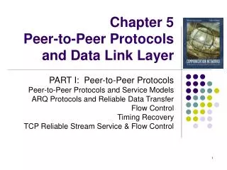
Ethernet “dominant” wired LAN technology: • cheap $20 for NIC • first widely used LAN technology • simpler, cheaper than token LANs and ATM • kept up with speed race: 10 Mbps – 10 Gbps Metcalfe’s Ethernet sketch Link Layer
Ethernet: physical topology • bus: popular through mid 90s • all nodes in same collision domain (can collide with each other) • star: prevails today • active switchin center • each “spoke” runs a (separate) Ethernet protocol (nodes do not collide with each other) switch star bus: coaxial cable Link Layer
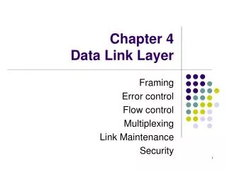
Ethernet frame structure sending adapter encapsulates IP datagram (or other network layer protocol packet) in Ethernet frame preamble: • 7 bytes with pattern 10101010 followed by one byte with pattern 10101011 • used to synchronize receiver, sender clock rates type dest. address source address data (payload) CRC preamble Link Layer
Ethernet frame structure (more) • addresses: 6 byte source, destination MAC addresses • if adapter receives frame with matching destination address, or with broadcast address (e.g. ARP packet), it passes data in frame to network layer protocol • otherwise, adapter discards frame • type: indicates higher layer protocol (mostly IP but others possible, e.g., Novell IPX, AppleTalk) • CRC: cyclic redundancy check at receiver • error detected: frame is dropped type dest. address source address data (payload) CRC preamble Link Layer
Ethernet: unreliable, connectionless • connectionless: no handshaking between sending and receiving NICs • unreliable: receiving NIC doesnt send acks or nacks to sending NIC • data in dropped frames recovered only if initial sender uses higher layer rdt (e.g., TCP), otherwise dropped data lost • Ethernet’s MAC protocol: unslotted CSMA/CD Link Layer
application transport network link physical fiber physical layer copper (twister pair) physical layer 802.3 Ethernet standards: link & physical layers • manydifferent Ethernet standards • common MAC protocol and frame format • different speeds: 2 Mbps, 10 Mbps, 100 Mbps, 1Gbps, 10G bps • different physical layer media: fiber, cable MAC protocol and frame format 100BASE-T2 100BASE-FX 100BASE-TX 100BASE-BX 100BASE-SX 100BASE-T4 Link Layer
5.1introduction, services 5.2error detection, correction 5.3multiple access protocols 5.4 LANs addressing, ARP Ethernet switches VLANS PPP Link layer, LANs: outline Link Layer
Ethernet switch • link-layer device: takes an active role • store, forward Ethernet frames • examine incoming frame’s MAC address, selectively forward frame to one-or-more outgoing links when frame is to be forwarded on segment, uses CSMA/CD to access segment • transparent • hosts are unaware of presence of switches • plug-and-play, self-learning • switches do not need to be configured Link Layer
Switch: multiple simultaneous transmissions • hosts have dedicated, direct connection to switch • switches buffer packets • Ethernet protocol used on each incoming link, but no collisions; full duplex • each link is its own collision domain • switching:A-to-A’ and B-to-B’ can transmit simultaneously, without collisions A B C’ 1 2 6 4 5 3 B’ C A’ switch with six interfaces (1,2,3,4,5,6) Link Layer
Switch forwarding table Q:how does switch know A’ reachable via interface 4, B’ reachable via interface 5? A B C’ • A:each switch has a switch table,each entry: • (MAC address of host, interface to reach host, time stamp) • looks like a routing table! 1 2 6 4 5 3 B’ C Q:how are entries created, maintained in switch table? • something like a routing protocol? A’ switch with six interfaces (1,2,3,4,5,6) Link Layer
Source: A Dest: A’ MAC addr interface TTL 60 1 A A A’ Switch: self-learning • switchlearnswhich hosts can be reached through which interfaces • when frame received, switch “learns” location of sender: incoming LAN segment • records sender/location pair in switch table A B C’ 1 2 6 4 5 3 B’ C A’ Switch table (initially empty) Link Layer
Switch: frame filtering/forwarding when frame received at switch: 1. record incoming link, MAC address of sending host 2. index switch table using MAC destination address 3. ifentry found for destinationthen { ifdestination on segment from which frame arrivedthen drop frame else forward frame on interface indicated by entry } elseflood /* forward on all interfaces except arriving interface */ Link Layer
Source: A Dest: A’ A’ A MAC addr interface TTL 60 60 1 4 A A’ A A’ A A’ A A’ A A’ A A’ A A’ Self-learning, forwarding: example • frame destination, A’, locaton unknown: A flood B • destination A location known: C’ selectively send on just one link 1 2 6 4 5 3 B’ C A’ switch table (initially empty) Link Layer
Interconnecting switches • switches can be connected together S4 S1 S3 S2 A F I D C B H G E • Q: sending from A to G - how does S1 know to forward frame destined to F via S4 and S3? • A:self learning! (works exactly the same as in single-switch case!) Link Layer
Self-learning multi-switch example Suppose C sends frame to I, I responds to C S4 S1 S3 S2 A F I D C B H G E • Q:show switch tables and packet forwarding in S1, S2, S3, S4 Link Layer
Institutional network mail server to external network web server router IP subnet Link Layer
network link physical link physical datagram datagram frame frame frame Switches vs. routers application transport network link physical both are store-and-forward: • routers: network-layer devices (examine network-layer headers) • switches: link-layer devices (examine link-layer headers) both have forwarding tables: • routers: compute tables using routing algorithms, IP addresses • switches: learn forwarding table using flooding, learning, MAC addresses switch application transport network link physical Link Layer
VLANs: motivation consider: • CS user moves office to EE, but wants connect to CS switch? • single broadcast domain: • all layer-2 broadcast traffic (ARP, DHCP, unknown location of destination MAC address) must cross entire LAN • security/privacy, efficiency issues Computer Science Computer Engineering Electrical Engineering Link Layer
7 1 2 8 15 9 10 16 VLANs Virtual Local Area Network port-based VLAN: switch ports grouped (by switch management software) so that singlephysical switch …… 15 7 9 1 2 8 10 16 switch(es) supporting VLAN capabilities can be configured to define multiple virtualLANS over single physical LAN infrastructure. … … Computer Science (VLAN ports 9-15) Electrical Engineering (VLAN ports 1-8) … operates as multiplevirtual switches … … Computer Science (VLAN ports 9-16) Electrical Engineering (VLAN ports 1-8) Link Layer
forwarding between VLANS:done via routing (just as with separate switches) • in practice vendors sell combined switches plus routers Port-based VLAN router • traffic isolation:frames to/from ports 1-8 can only reach ports 1-8 • can also define VLAN based on MAC addresses of endpoints, rather than switch port 15 7 9 1 2 8 10 16 • dynamic membership: ports can be dynamically assigned among VLANs … … Computer Science (VLAN ports 9-15) Electrical Engineering (VLAN ports 1-8) Link Layer
1 16 VLANS spanning multiple switches • trunk port:carries frames between VLANS defined over multiple physical switches • frames forwarded within VLAN between switches can’t be vanilla 802.1 frames (must carry VLAN ID info) • 802.1q protocol adds/removed additional header fields for frames forwarded between trunk ports 15 7 9 7 1 3 5 2 8 10 4 6 2 8 … … Computer Science (VLAN ports 9-15) Ports 2,3,5 belong to EE VLAN Ports 4,6,7,8 belong to CS VLAN Electrical Engineering (VLAN ports 1-8) Link Layer
802.1Q VLAN frame format type source address dest. address preamble data (payload) 802.1 frame CRC type 802.1Q frame data (payload) CRC 2-byte Tag Protocol Identifier (value: 81-00) Recomputed CRC Tag Control Information (12 bit VLAN ID field, 3 bit priority field like IP TOS) source address dest. address preamble Link Layer
5.1introduction, services 5.2error detection, correction 5.3multiple access protocols 5.4 LANs addressing, ARP Ethernet switches VLANS PPP Link layer, LANs: outline Link Layer
Point to Point Data Link Control • one sender, one receiver, one link: easier than broadcast link: • no Media Access Control • no need for explicit MAC addressing • e.g., dialup link, ISDN line • popular point-to-point DLC protocols: • PPP (point-to-point protocol) • HDLC: High level data link control (Data link used to be considered “high layer” in protocol stack!
PPP Design Requirements [RFC 1557] • packet framing: encapsulation of network-layer datagram in data link frame • carry network layer data of any network layer protocol (not just IP) at same time • ability to demultiplex upwards • bit transparency: must carry any bit pattern in the data field • error detection (no correction) • connection liveness: detect, signal link failure to network layer • network layer address negotiation: endpoint can learn/configure each other’s network address
PPP non-requirements • no error correction/recovery • no flow control • out of order delivery OK • no need to support multipoint links (e.g., polling) Error recovery, flow control, data re-ordering all relegated to higher layers!
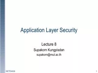
PPP Data Frame • Flag: delimiter (framing) • Address: does nothing (only one option) • Control: does nothing; in the future possible multiple control fields • Protocol: upper layer protocol to which frame delivered (e.g., PPP-LCP, IP, IPCP, etc)
PPP Data Frame • info: upper layer data being carried • check: cyclic redundancy check for error detection
Byte Stuffing • “data transparency” requirement: data field must be allowed to include flag pattern <01111110> • Q: is received <01111110> data or flag? • Sender: adds (“stuffs”) extra < 01111110> byte after each < 01111110> data byte • Receiver: • two 01111110 bytes in a row: discard first byte, continue data reception • single 01111110: flag byte
Byte Stuffing flag byte pattern in data to send flag byte pattern plus stuffed byte in transmitted data
PPP Data Control Protocol Before exchanging network-layer data, data link peers must • configure PPP link (max. frame length, authentication) • learn/configure network layer information • for IP: carry IP Control Protocol (IPCP) msgs (protocol field: 8021) to configure/learn IP address
principles behind data link layer services: error detection, correction sharing a broadcast channel: multiple access link layer addressing instantiation and implementation of various link layer technologies Ethernet switched LANS, VLANs virtualized networks as a link layer: MPLS synthesis: a day in the life of a web request Chapter 5: Summary Link Layer
journey down protocol stack complete(except PHY) solid understanding of networking principles, practice ….. could stop here …. but lotsof interesting topics! wireless multimedia security network management Chapter 5: let’s take a breath Link Layer