Download
1 / 1
20 likes | 153 Vues
Protein Assembly at the Air-Water Interface Arjun G. Yodh , University of Pennsylvania, DMR 0520020.

E N D
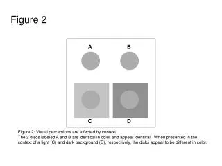
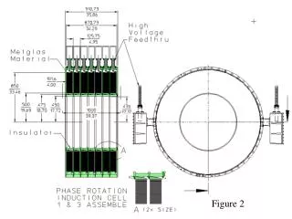
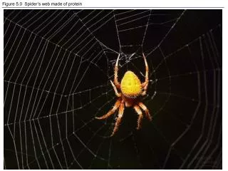
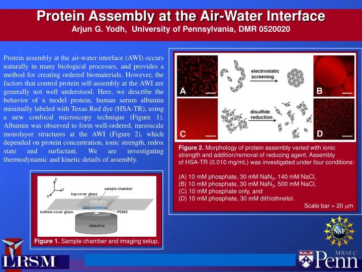
Protein Assembly at the Air-Water InterfaceArjun G. Yodh, University of Pennsylvania, DMR 0520020 Protein assembly at the air-water interface (AWI) occurs naturally in many biological processes, and provides a method for creating ordered biomaterials. However, the factors that control protein self-assembly at the AWI are generally not well understood. Here, we describe the behavior of a model protein, human serum albumin minimally labeled with Texas Red dye (HSA-TR), using a new confocal microscopy technique (Figure 1). Albumin was observed to form well-ordered, mesoscale monolayer structures at the AWI (Figure 2), which depended on protein concentration, ionic strength, redox state and surfactant. We are investigating thermodynamic and kinetic details of assembly. Figure 2. Morphology of protein assembly varied with ionic strength and addition/removal of reducing agent. Assembly of HSA-TR (0.010 mg/mL) was investigated under four conditions: (A) 10 mM phosphate, 30 mM NaN3, 140 mMNaCl, (B) 10 mM phosphate, 30 mM NaN3, 500 mMNaCl, (C) 10 mM phosphate only, and (D) 10 mM phosphate, 30 mMdithiothreitol. Scale bar = 20 mm Figure 1. Sample chamber and imaging setup.