Download
1 / 15
150 likes | 164 Vues
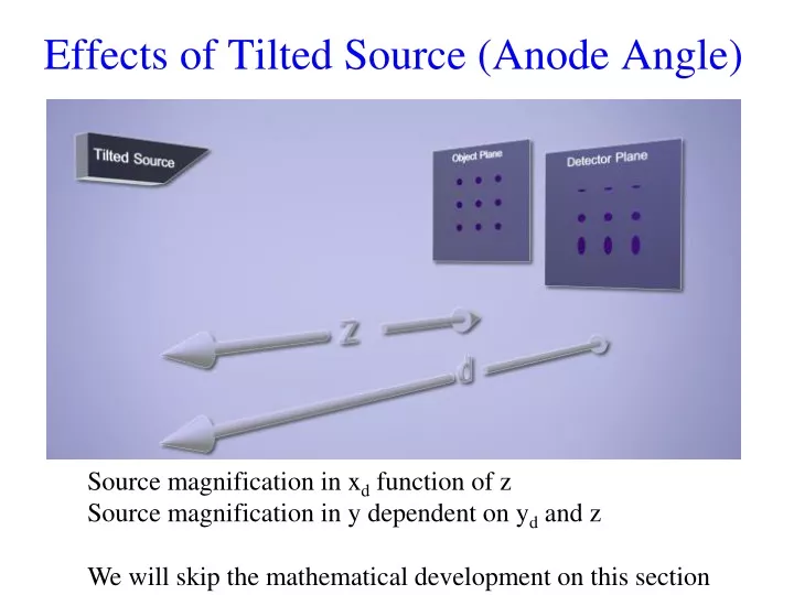
Effects of Tilted Source (Anode Angle). Source magnification in x d function of z Source magnification in y dependent on y d and z We will skip the mathematical development on this section. s (x s , y s , z s ) Consider a 3 x 3 array of pinholes. t(x,y) = d (0,y – c) + d (0,y + c).

E N D
Effects of Tilted Source (Anode Angle) Source magnification in xd function of z Source magnification in y dependent on yd and z We will skip the mathematical development on this section
s (xs, ys, zs) Consider a 3 x 3 array of pinholes t(x,y) = d(0,y – c) + d(0,y + c) Id (yd) ys y c anode t 0 -c z d t(x,y) above can be considered a lead plate with two pinholes punched into it. 3 x 3 array of circular pinholes to left shows how source is contracted in y for positive y detector positions and enlarged for negative detector locations. y x
Let’s allow the magnification to be different on each axis. The pinhole models an object, d(x’, y’,z). M’x’ + m’ xs, M’y’ + m’ ys The diagram above merely shows how one point in the source, the pinhole, and the detector are related by geometry. Here we use a M’ to allow for magnification of the pinhole, and m’ to allow for magnification of the source d (x’, y’,z) ys z d Detector Plane
We will consider the impulse response using a pinhole at x’, y’. where is a collection efficiency for the pinhole: =Ω/4π d2
If tan () = a, then the source position z’ = a ys By geometry, object magnification is M’ = (d - ays)/(z - a ys) Source magnification is m’ = - ((d - a ys) - (z - a ys)) / (z - a ys) m’ = - (d - z)/ (z - a ys) d (x’, y’) (xd, yd) ys z d ays
Recall xd = M’x’ + m’xs yd = M’y’ + m’ ys Mx = xd /x’ = M’ = (d - a ys)/(z - a ys) ≈ d/z since for practical arrangements d, z >> ays Typical dimensions: z, d ~ 1 m, ys ~ 1mm Similarly My = yd /y’ ≈ d/z mx = xd /xs = m’ ≈ - (d-z)/z = m my = yd /ys This is more interesting derivative since both M’ and m’ are functions of ys my = yd /ys = (M’ y’)/ ys + (m’ ys)/ ys
From previous slide, M’ = (d - a ys)/(z - a ys) and m’ = - (d - z)/ (z - a ys) To find : my = yd /ys = (M’ y’)/ ys + (m’ ys)/ ys my = [((z- ays)(- a) - (d - a ys)(- a)] y’)/(z - a ys)2 + -(d-z) • [(z- a ys) - ys(- a)]/ (z- ays)2 = (- a[z-d] y’ - (d -z) z)/ (z- ays)2 = - (d - z) (z - ay’)/ ((z- ays)2 my = - (d-z) (z - ay’)/ z2 = m (1- (ay’/z)) Using this relationship and ignoring obliquity, How does magnification change with object position?
Since system is linear, we can write a superposition integral. Id (xd, yd) = ∫ ∫ h ((xd, yd, x’, y’) t(x’,y’) dx’ dy’ =
For developing space-invariance, let’s consider a magnified object Let Not a space-invariant system since 1- (ay’’/Mz) varies slowly with y’’ or y’ But it doesn’t vary much in a region of an object.
y’ Let y’d = My’ Object Detector Consider a horizontal strip across the detector centered at For this region, ay’’ = aMy’ = ayd where Mz = d Here is a constant over a region in the detector during the convolution.
At ay’= z, source width goes to 0 in y. We call this the “heel effect” Anode In the frequency domain, Detector plane Id Electron beam
Effect of Motion Let’s consider object motion with constant velocity in the x direction over the imaging time T at velocity v Over time T, the object size will change position in the detector plane by MvT vT MvT
The impulse response due to movement in x is Notice that there is no degradation in y, as we expected. The complete impulse response is given below( a planar source parallel to the detector is used here for simplicity). Blur in x direction gets minimized as T decreases to 0
How to minimize Motion blurring Assume a L x L source parallel to detector Write energy density Es as a power integrated over time p(xs, ys) is regional source power density (it is limited by tungsten melting point). Set p (xs, ys) = Pmax. Operating tube at maximum power available. T is the time beam is ON Es = ∫∫∫ p (xs, ys) dxs dys dt=PmaxTL2 , then If L increases, source grows, then T can decreases. Complete Response function for Rectangle Source and movement MvT in x direction:
We have extension of the impulse response in the x direction as: X = |m|L + (MvEs/ Pmax L2) by the convolution of two rectangles, due to source blurring and motion We could choose to minimize several criteria. Area, for example. We will simply minimize X now with respect to L. Corresponding Exposure Time at Optimal L If v = 0, then L = 0 T = ∞ no source blurring If |m| = 0, object is on detector L ∞ T = 0